
Since the late 1900s, the RP-SMA connector has gained massive popularity more than SMA. As a result of this, you have a wide range of options for RP SMA antenna. Why was the RP-SMA connector easier to use in most incompatible coax cables? You first need to understand the basic terminologies of antenna connectivity to grab the whole concept.
Table of Contents
- Properties of Antenna
- RP-SMA Antenna– Why are Antenna Connectors necessary?
- RP-SMA Antenna– SMA Connectors
- The RP-SMA Connector
- Conclusion
Properties of Antenna

Caption: A typical Antenna
The basic features that can define the efficiency of an antenna are as follows.
Gain
Gain is the measure of the intensity of waves that the antenna transmits in a particular region. The manufacturers design the antenna so that it can emit maximum power in the direction you want it. Thus, you also need to understand the concept of how “directivity” affects the gain.
In mathematical terms, you can define gain as
Gain= Directivity * Efficiency
Directivity is the signal strength of an antenna in a specific direction. And the efficiency tells how much power loss is made due to faults and resistance in the equipment.
Bandwidth
The frequency range on which the device can correctly operate is termed the bandwidth. Moreover, the bandwidth, measured in Hz, should be optimal so that the standing wave ratio is less than 2.1.
Polarization
The electromagnetic polarity of the field that a working antenna creates in a region is known as its polarization. While communicating between two devices, you have to consider the polarity as a crucial measure, and it is because every device has a different direction of polarity.
When dealing with horizontal waves emitting equipment, you also need horizontal signal polarity on the receiver side. The same stands for the situation when you have vertically polarized radiations. Sometimes, you might need the circular polarization technique, which requires both horizontal and vertical polarity waves.
Effective Length
Effective length is the parameter of an antenna through which the waves can bounce back. Hence, for higher wavelengths, the more significant the effective antenna length, the higher the efficiency of the signals. Additionally, you need to measure the effective length for the sender and the receiver end as well.
The following formula measures the effective length
Effective Length = (Distribution of non-uniform area)/ (Uniform current distribution area)
RP-SMA Antenna– Why are Antenna Connectors necessary?
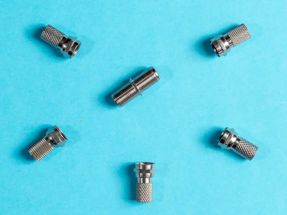
Caption: Various types of Antenna connectors
Antenna connectors are the tiny radio frequency regulator attached at the termination points on an antenna. By using connectors, signals without any significant power loss due to any factor are possible.
Although the antenna connectors may not seem like an essential part of the antenna assembling process, the reality is different. Without connectors, you cannot maintain the crucial chain of radiofrequency connections within a wireless communication system. Thus, the flow of waves across a specific area is always dependent on the use of connectors.
Higher is the quality of the connectors you choose for an antenna device; maximum is the performance. Otherwise, the system will face the loss of data due to connectivity impairment.
Moreover, the structural and mechanical properties of an antenna connector play a considerable part in better performance. So, depending on the size of the antenna connector, you will place the device in case of space problems. If not mounted properly, it may fail the antenna and consequently the failure of the whole machine.
RP-SMA Antenna– SMA Connectors
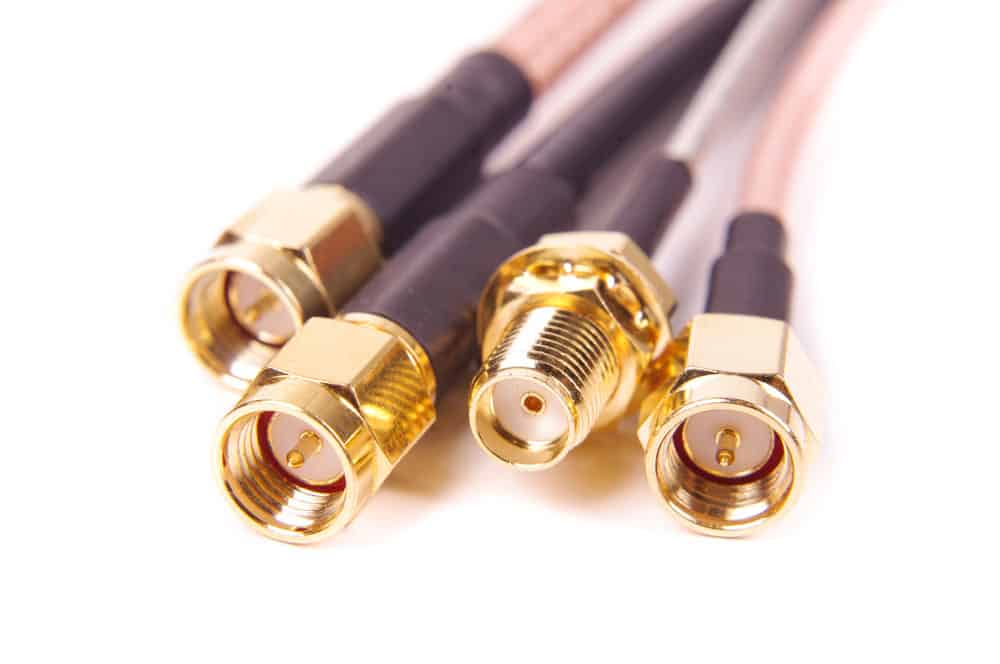
Caption: A typical SMA Connector
The SMA stands for Sub-Miniature type A, designed in the late 1960s as military usage SMA equipment. It is a connector comprised of semi-precision, miniature threads. You can use an SMA connector when dealing with varying frequency systems.
For robust connectivity, the antennas use a Female or Male threaded SMA connector. While establishing a connection, you will connect both counterparts terminating the antenna and the cable using a hex nut. Thus, you will get more regular communication in the system.
Physical Specifications
A basic, military standard MIL-STD-348 calls for some specific product description that most manufacturers follow. The SMA connector is composed of a ¼-inch barrel with 36 conductive threads per inch.
An SMA adapter is based on two complementing coaxial connectors:
- SMA Male connector with 5/16 inch hex nut to tighten up the internal thread and the center pin within the interface of the female side
- SMA Female connector with external threads and a mating interface consisting of a receptacle
The antenna manufacturers usually make the body and the coupling terminal of the SMA connector with brass or stainless steel. They make the inner interface with brass or copper while insulating the whole body with a PFTE insulator. Few SMA designs may call for the use of a silicon rubber gasket to ensure weather shielding. In proper connectivity, an SMA connector has a rating of 500 mating cycles.
Electrical Specifications
- Frequency of up to 18GHz
- The impedance of 50 OHMS
- Operating Voltage up to 500 Volts
- VSWR of 1.15+0.1f
- Radio Frequency Leakage of up to 90dB per minute at frequency range 2-3 GHz
Applications
In recent years, SMA connectors have been a choice. Most engineers prefer establishing connections in wireless communication devices. Here are some applications we have observed over the time
- You can find its ports on every PCB interface board since it goes well with the wireless antennas’ flexible, semi-rigid coax cables.
- Cellular communication prefers SMA connectors because of their smaller size and highly robust performance at the micro frequency range. Therefore, SMA connectors terminate many cellular antennas.
- GPS antennas also prefer using SMA over any other type of connectors as they can tolerate outdoor conditions
- WIFI antennas have also been observed to be using the SMA connectors recently.
The RP-SMA Connector
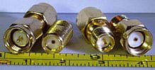
Caption: Comparison between RP-SMA and SMA Connector
RP-SMA Antenna connectors are the variant of SMA connectors, identical in both electrical and mechanical performance. Many WIFI antenna systems used the standard SMA as a source of connectivity. Yet, there were non-compatible antennas for which you need a coax connector of a particular type.
Names of the connector can be the same. But, the only difference between the two is the reversal of mating interfaces between the RP-SMA male and female connector. Thus, you get a reverse polar system.
RP-SMA got popular with the rise of wireless devices. The US Federal Communication Commission thought that such high usage of SMA would lead them into problems. Hence, using a look-alike connector, they wanted to prevent unauthorized connections with the antenna and raise the power supply range. However, the RP-SMA has also become available everywhere, just like its other counterpart.
RP-SMA Antenna– Physical Features
The RP-SMA is a threaded connector, just like its SMA variant, and mates using screw coupling. Similarly, RP-SMA connectors consist of 36 conductive threads per inch and use a hex nut for securing the connection. Also, the manufacturers use the same material and fabrication methods for the production of RP-SMA. Yet, it differs in polarity due to reversed mating interface.
Here, the RP-SMA is based on
- RP-SMA male connector with internalized threading, a hex nut, and a socket instead of a center pin.
- RP-SMA Female connector with external threading, but carry a center pin to insert into the socket of the male connector.
Therefore, you must be looking out for the mating interface in the RP-SMA male and female and determine the connector type. If you do not do it at the time of connection, the system may not be working like it is supposed to work.
RP-SMA Antenna– Electrical Specifications
- Frequency of up to 18GHz
- The impedance of 50 OHMS
- Operation Voltage rating up to 500 Volts
- VSWR of 1.15+0.1f
- Radio Frequency Leakage of up to 90dB per minute at frequency range 2-3 GHz
RP-SMA Antenna–Applications
The primary application of such connectors is to prevent the high-gain antennas from connecting the consumer equipment. It is found in
- WIFI devices
- Cellular 3G, 4G LTE devices
- WLAN devices
Although they are found on much WIFI-associated hardware, you have to take care of any SMA’s working parallel. Hence, if you disconnect the wireless antennas from the device for any reason, the RP-SMA can replace the job.
Conclusion
From the above, you can see RP-SMA or reverse polarity SMA is a connector found in most WIFI devices to connect different coax cables. Also, the change in polarity prevents the high gain antenna from connecting with irrelevant modules. Here at Cloom, we have special offers with a wide range of connectors and cables to support your antenna system. So, feel free to contact us now.