
If you have a lot of work around coax cables, you know a wide variety. You can get the most common impedances: 50 Ohm and 75 Ohm, which we use as video or antenna cables. However, the range starts from 32 ohms and goes up to 124 ohms generally. Among them, the 50-ohm coaxial cable can carry out the power and voltage signals just like the output of a transmission circuit. It is the standard specified on most of the appliances. This article will see how it has proven to be a better choice in some cases and its research.
Table of Contents
- History of 50-Ohm Coax Cable
- Why 50-Ohms standardization?
- Why 75 Ohms?
- 50 vs. 75 Ohms, Which one suits you best?
- Conclusion
History of 50-Ohm Coax Cable
The standardization process dates back to the early 1930s. It was the time when the young scientists were searching on Telecom best practices. They were designing “air-filled coaxial cables” to transfer several kilowatts of power from radio transmitters. The engineers have a few objectives, to have the highest authority and voltage transfer, with the lowest possible loss.
As the research moved forward, the scientists concluded that it is impossible to gain all three benefits since
Less attenuation or loss
the internal dielectric requires 77 Ohms for most air-filled coax cables, and it might work on 50-ohm for other wires as well.
The highest voltage
Between the center and outer conductor of the air, dielectric coax cables need 60-ohms impedance approx.
Maximum power transfer
Maximizing the impedance at about 30-ohms.
Note that the transfer has to be done across hundreds of miles. For that, you will need long transmission lines spread over the distances. However, as the distance increases, the power handling capabilities are lessened.
As you can see, not all the three objectives match each other in impedance. In other words, you cannot have the highest power and voltage transfer, with less loss, all on one impedance value. Thus, you have to consider some tradeoffs while choosing an option.
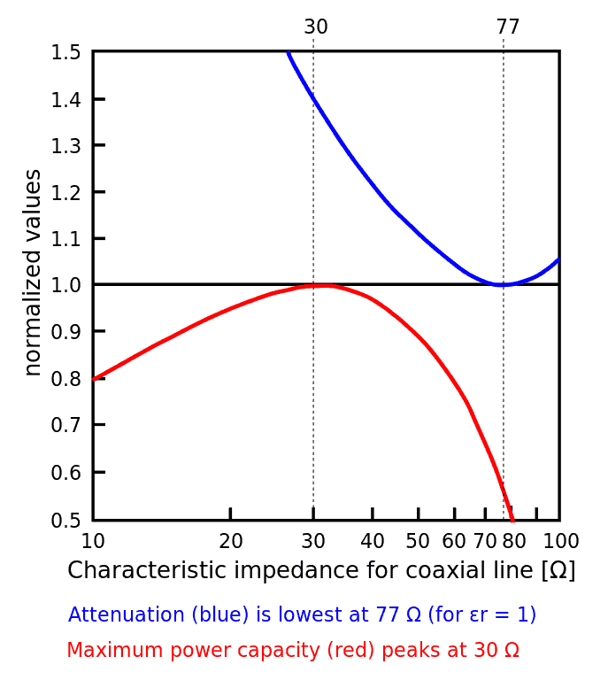
Caption: Characteristic Impedance of Coaxial Line (Ω)
Source: https://go.skimresources.com?id=222265X1706442&xs=1&url=https%3A%2F%2Fwww.altium.com%2F
Why 50-Ohms standardization?
As you have read above, 50 Ohm is a good tradeoff between power handling and loss control in an air dielectric coax. Following are some mathematical arguments to support our say.
Cable Loss vs. Impedance
For typical RF signals, you will use the circumferential area of the conducting wire to determine the resistance per unit length. The following loss/length equation can help you out in checking the ratio.
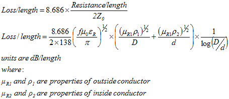
Caption: The Loss/Length Calculation
You can see the detailed derivation here.
As you can see the factor 1/d in the equation, you might think that the greater the circumference of a cable, the lesser the loss. But it is the other way around since you cannot ignore the “log” before it. As you solve this equation, you will come to know that the increasing value of d increases the characteristic impedance Z0.
To plot a simple loss/length versus characteristic impedance, you must calculate the coaxial cable impedance. If you know the inner diameter and dielectric, you can use the equation as follows,
Z0= 138RDd ohms
As you plot the loss/length vs. impedance, you will see that the minor loss an air dielectric coax can have is around 77 Ohms. Here the D/d value was approximately 3.5, and the inner diameter was 10mm. With all these values, the loss will be a total is 10GHz.
Remember that the air dielectric coax can have the lowest possible loss. But it cannot be the same as air cannot always support conduction. In the case of any other dielectric, you need to add its own dielectric constant.
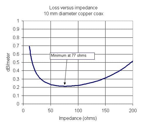
Caption: Loss VS impedance of a 10mm copper cable.
Source: https://www.microwaves101.com/
Peak power handling
Peak power handling of a coax heavily relies on the limit of breakdown voltage. However, as the cable is cylindrical, you cannot lessen the voltage surge by increasing the distance between the inner wire and the outer conductor surface.
Here is the equation to explain the field enhancement in round cables
β= arln 1+ar
Where a is the gap between the conductors and the r is the radius of the inner conductor.
To calculate the highest power handling, you can assume that the electric field will not maximize. Then, you can calculate the area created across the gap of cable. Next, apply the above equation and calculate the max power by
Power= Vcritical2/2Z0
Here, the Critical is a peak value, not an RMS value. In the below graph, you can observe that the power is a maximum of 30 Ohms.
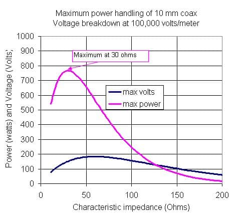
Caption: Maximum Power Handling of a 10mm coax cable
Source: https://www.microwaves101.com/
Is 50 Ohms a considerable impedance?
The above mathematics shows that the lowest attenuation is 77 Ohms, whereas the highest power gain is 30 ohms. Take the simple average of both these values, and you will get 53.5 Ohms. Also, the geometric mean of 77 and 30 is 48, which is again near 50 ohms. These values suggest the range of impedance, where you will not compromise both power and signal loss. Thus, you can choose the 50-ohm as a standard in the case of air dielectric.
You can also consider using PFTE as a dielectric between the cable as it can handle 10s kilowatt of power. PFTE-filled coaxial cable can have the minimum power loss on about 50-ohm impedance. So, this could be another explanation of why the 50-ohm is a standard.
Why 75 Ohms?
As you see, on 77 Ohms, the air dielectric coax has the lowest loss of power. Hence the engineers round off the values, and you see 75-Ohm RG-6 cable in the market. But as you go for the PFTE foam cables, the dielectric constant is 1.43. Here, the loss impedance will be around 64 ohms.
Then why 75 ohms? It is because the center conductor can be made of steel with some copper plating. The dielectric constant rises to 2.2, and thus the impedance rises. Keeping the 75 Ohms impedance then makes you compromise between the low loss and cable flexibility.
50 vs. 75 Ohms, Which one suits you best?
While discussing the choice between 50 or 75 ohms, there are two main factors, impedance, and power. For example, a 50-ohm cable works much better for boosting cellular signals. On the other hand, 75 Ohm cable will do the best for you if the frequency range is higher.
Therefore, every usage of coaxial cable requires a deep understanding of what the requirements are. Following are some of the points you can consider while choosing between the two.
When to choose 75-Ohms
- The cable is under 50 ft long.
- The area you wish to cover is under 5000 square ft.
- Someone has already prewired the house with F-connectors
- If the application area is a home or a small building
When to choose 50-Ohms
- The cable is over 100 ft long.
- The area you wish to cover is around 7500 to 100000 square ft.
- The client wants the best power solution.
- If the application area is a building or any commercial area
Conclusion
The 50-ohm impedance standard comprises several types of research, and it is the midway the engineers could adopt to have the maximum power with minimum energy losses. The prototype is tested only on on-air dielectric cables but applies to PFTE and other materials as well. Here at Cloom, we offer custom wiring assembly with attention to detail. To avail of our services, contact us now.