
There are many uses for alternators, including:
- Cars rely on alternators to power the entire circuit and recharge the battery whenever the engine operates.
- Alternators are one type of electric generator that you can use to keep the lights on in the event of a blackout.
- Also, alternators have several practical uses in the industry, including operating fans, pumps, and conveyor belts.
Alternator derives its roots from the same word allowing you to convert the mechanical energy into a current, mostly in vehicles. However, it would help if you looked into an alternating wiring diagram to understand.
Table of Contents
- What is an Alternator?
- How the Alternator and Charging System Work
- Alternator Wiring Harness Overview
- Alternator Wiring According to the Voltage Regulator Types
- How Many Wires Go to an Alternator?
- Typical Alternator Wiring Steps
- Conclusion
What is an Alternator?
The car’s alternator is a crucial component yet requires no regular maintenance. It uses alternating current as its source to transform mechanical energy into electricity and then converts it to direct current.
An alternator’s principal purpose is to help the battery power the vehicle’s electrical components, including the headlights, fan, and windshield wipers. It converts the AC to DC and adjusts the voltage so that each device receives the minimum power it needs to function.
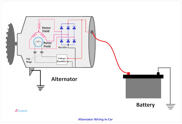
Caption: Alternator wiring in a car
Source: blogspot.com
How the Alternator and Charging System Work
The stator, the rotor, and the rectifier bridge are the three main parts of an alternator.
- The alternator’s rotor uses wire coils that wind around two sets of magnetic poles that rotate in opposite directions.
- The stator has three groups of coil windings that remain in one place and a laminated core.
- Diodes in the rectifier bridge prevent electricity from flowing in the wrong direction.
The field coil on the rotor is supplied with electricity via slip rings and brushes on the shaft. The rotor’s magnetic poles amplify the current’s magnetic field.
A pulley on the front of the alternator is connected to the rotor via the vehicle’s drive belt, which spins it when the engine is running. An alternating current is generated in the stator due to the rotor’s rotation. The rectifier bridge changes the AC power into DC power suitable for the vehicle’s electrical components.
Moreover, charging the battery requires an alternator to generate enough electricity without damaging the vehicle’s electronic components. As a solution, you can manage the alternator’s output by adjusting the current via the rotor’s field coil.
Alternator Wiring Harness Overview
Alternator wiring is the primary source of transferring the power to the battery from an alternator. These wires are of copper or aluminum, with protective insulation on them.
- Gauge: For using the wire in the alternator, you need to choose the right size. If not, the connection may become loose or not fit properly in the terminal. Thus, you have to choose between 10, 12, and 14 gauge sizes.
- Colors: Most common color for high voltage wire is “red.” However, it can be in green or blue. The other wire or ground is black, connecting to the car’s metal surface and providing a grounding path.
- Terminals: The wire harness of the alternator comprises two types of terminals, a ring, and a spade. The Spade terminal connects the alternator to the wire, and the call connects the wire to the battery.
Alternator Wiring According to the Voltage Regulator Types
The alternator must charge the battery using enough voltage. However, the voltage should not exceed the limit to damage the car’s electrical system. Thus, manufacturers set up voltage regulators to control the current flowing to the rotor’s coil.
Alternator Wiring with electromechanical regulators
Some older automobiles have an electromagnetic voltage regulator. Moreover, these regulators consist of the cutout relay, regulator, and current regulator. Every part has its unique function.
Cutout relay connects alternator to battery to charge it. It opens to prevent discharge into the alternator. The current regulator manages the alternator’s field circuit. The regulator controls the field circuit, regulating its voltage output.
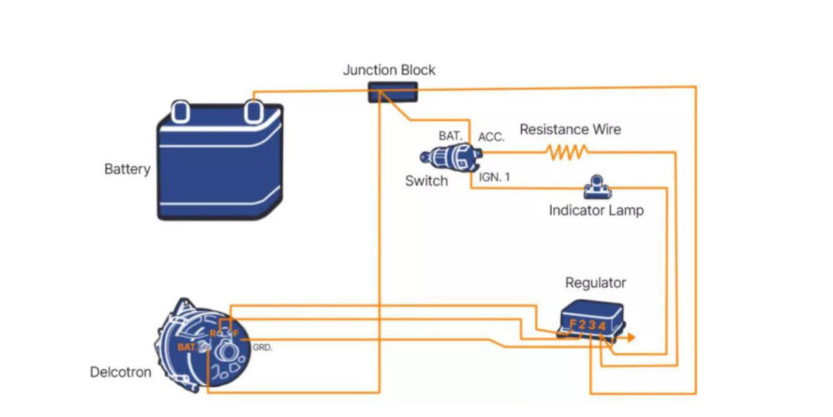
Caption: Alternator-wiring diagram with the electromagnetic regulator
Source: https://www.carparts.com/
Alternator Wiring with Electronic Voltage Regulator
Electronic regulators (Zener diodes and transistors) control the alternator output. The regulator operates the alternator by actuating the field circuit’s grounding. It affects current flow.
Electronic regulators lack moving parts, unlike electromechanical ones. Solid-state architecture offers faster cycling and more fine alternator regulation. Moreover, you can mount the Internal and external electronic regulators.
System design determines which wires route to an alternator; However, the one without a computer will have three inputs. These terminals can charge the battery voltage and control the system’s ignition.
Caption: Alternator-wiring diagram with the internal electronic regulators
Source: https://www.carparts.com/
Alternator Wiring with control module voltage regulation
The powertrain control module (PCM) controls alternator output in many late-model automobiles. Most modules employ an inbuilt driver to switch the alternator’s field circuit. GM’s EPM system is an example. This alternator has a non-serviceable internal regulator. Moreover, PCM direct output by varying field coil on time.
PCMs control alternator power in many late-model automobiles. It determines charging voltage levels based on body control module data (BCM). A data network connects BCM and monitors a sensor to track the battery current. If the EPM system fails, a message is transmitted via the data network to switch on one or more led indicators.
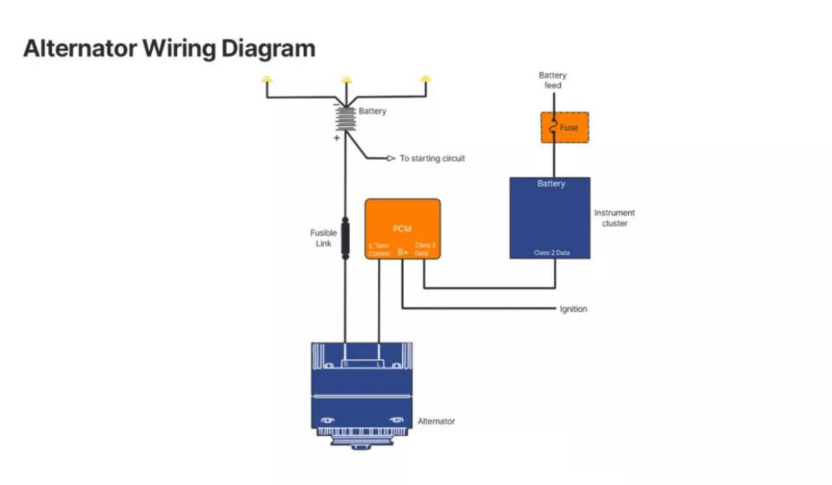
Caption: wiring diagram of PCR-controlled alternators
Source: https://www.carparts.com/
How Many Wires Go to an Alternator?
The alternator’s current and voltage are purpose and type-specific. Still, automotive alternators generate 50-100 amps at 13-15 volts. Most alternators feature three or four terminals for wiring connections.
3-wire alternator Wiring Diagram
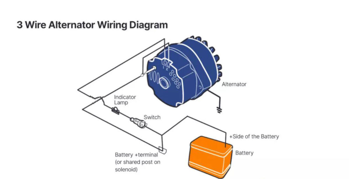
Most people refer to a standard General Motors alternator with an integrated regulator as a 3-wire alternator, often known as a 3-pin alternator. It is an upgrade over the 1-wire variety and may be installed in earlier vehicles. The voltage at the fuse box and the ignition are monitored by the 3-wire alternator, which then adjusts the charge output as needed. Moreover, the positive wire attaches to the alternator’s wire post via a screw rather than a plug.
The first red wire is the positive battery cable. It connects directly to the battery or to a junction box where other lines link to the battery. You’ll find the second and third wires, also known as terminal wires, right next to one another. The exciter/ignition input wire is at terminal 1, while the voltage detecting wire is at terminal 2. The negative cables require special care.
The primary grounding connection is the negative wire.
One alternator’s main negative cables will go straight to the vehicle’s chassis. The electrical interference and the sense wire’s connection are improved by its use.
The battery positive terminal of the main power cable links to the device’s output
It would help if you connected an alternator’s positive primary wire to the unit’s output port, located at its rear. It is the connection point between the alternator and the battery, where power is stored.
Sensor links the alternator through the sense wire
It would help if you connected an alternator’s sense wire to the battery terminal to communicate with the voltage regulator. The regulator can use the voltage reading to control the alternator’s output.
The ignition indicator connects to the field ignition wire.
The warning light for the ignition is linked to the alternator’s field ignition input wire. The alternator wouldn’t function without the ignition wire.
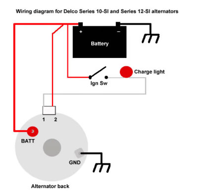
Caption: Wiring diagram of 3-wire alternator
Source: https://www.greentractortalk.com
1-wire alternator Wiring Diagram
A 1-wire alternator has a self-exciting regulator. Both of the extra ports on the regulator are unnecessary. Thus there is no need to run a wire to the regulator to complete the turn-on loop with the ignition.
The self-exciting nature of the 1-wire alternator means it won’t begin charging until the engine speed reaches a certain point. You may have problems keeping up with the car’s electrical needs if you combine this need with a delayed cruise around a show or a sophisticated fuel-injection configuration that adjusts starter parameters.
The major drawback of a one-wire alternator is that it does not begin charging until a certain engine RPM has been reached, necessitating revving the engine. The size of the pulleys and the alternator’s internals determine how many revolutions per minute are necessary to initiate the process. While starting a fuel vehicle may or may not achieve that threshold RPM. However, when creating a standard carbureted engine, you will likely pump the gas or use the choke.
The three-wire alternator detects power at the ignition and fuse box and charges more to get everything running. The 1-wire alternator can only sense its supply point: the battery. Moreover, if the power source is good, it won’t notice a dip in voltage.
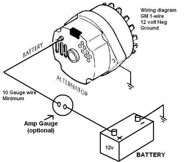
Caption: Wiring diagram of a 1-wire alternator
Source: https://www.greentractortalk.com/threads/86-jd-950-changing-alternator-to-a-one-wire-system.210005/
1-wire or 3-wire alternator: What’s best for me?
While you probably won’t be confused over which alternator provides the best performance, having a tangled mess of wires under the hood may give you pause. Despite its intimidating name, the 3-wire system requires two additional cables to be added to the existing electrical setup. The 3-wire alternator gives you more peace of mind unless you want to limit your electric cost rigorously when traveling at low RPM.
Typical Alternator Wiring Steps
The wiring of a typical alternator needs the following steps;
- Check the number of the terminal on the alternator; these can be three or four. If you are looking under the hood, you can do it with a flashlight.
- Determine the position of terminal B, “Bat,” or “Pos.” The positive terminal of the alternator uses a red wire for connection.
- Find the terminal F, “Neg,” or “field.” It is the ground terminal of the alternator that connects via a black wire. Moreover, the other end of the wire attaches to the car’s metal surface to provide a grounding path to the current.
- Next, check for the terminal “Ign” that connects the dashboard’s ignition or warning system. The wire here can vary in color.
There can be a fourth terminal for the voltage regulator. However, modern vehicles have a built-in regulation system, so you might not find this terminal here.
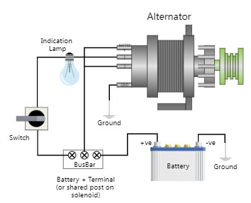
Caption: Wiring diagram of 3-wire alternator
Source: https://www.edrawmax.com
Conclusion
The alternator is an essential system for any car. Its wiring differs from vehicle to vehicle; thus, you must consider different wiring standards. Here at Cloom, we offer wiring harnesses and cable assemblies to make your connection safe and reliable.