
A receiver’s effectiveness is a crucial factor to consider when you’re handling any wireless transmitting system. After all, if you have interference in your received signals, it may disruptor your network service.
So, as a designer, you need to design, test, and implement your network system to meet certain technical specifications.
That way, your design would stand a better chance of working correctly. Intermodulation distortion is the primary factor to consider when implementing your network.
This article will give you a comprehensive view of intermodulation distortion.
Table of Contents
- What Is Inter Intermodulation Distortion?
- Types of Intermodulation Distortion
- How Does Inter modulation Distortion Work?
- Why Is Inter modulation Distortion Important?
- Inter Modulation Distortion–How to Avoid Intermodulation Distortion
- Final Thoughts
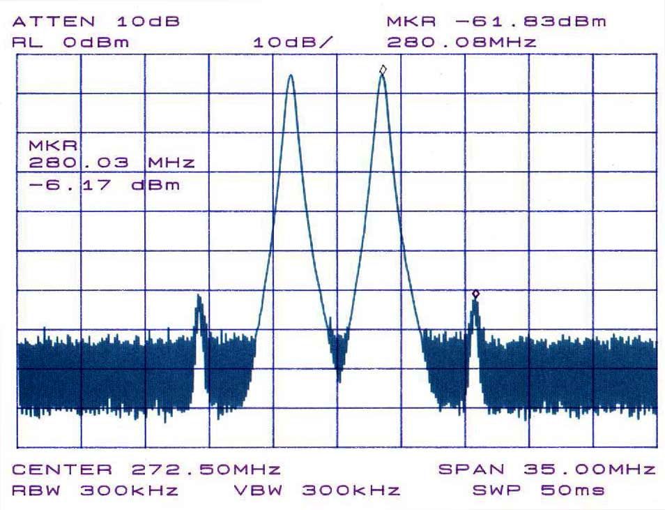
RF Intermodulation at 280MHz
Source: Wikimedia Commons
What Is Inter Intermodulation Distortion?
The intermodulation distortion or IMD happens when two or more nonlinear frequencies blend. As a result, the spectrum produces extra signals and its original signal within its harmonics.
In other words, the nonlinear range system gives out additional output signals. And it’s inclusive of the difference and sum of the input signals.
Here’s an example to give you a clearer understanding:
A nonlinear device with two input voltage RF frequencies RF1 and RF2, outputs the following:
- RF1 + RF2
- RF2 – RF2
- 2RF2
- And 2RF1
In other words; RF1 RF2 = (RF1 + RF2) (RF2 – RF2) (2RF2) (2RF1)
So, RF1 + RF2 and RF2 – RF2 is the second-order intermodulation frequencies. In contrast, the 2RF2 and 2RF1 are the harmonics—which are mockup signals. Hence, they show up as multiple numbers of the significant input signals.
Types of Intermodulation Distortion
There are two types of intermodulation distortion.
Active Intermodulation Distortion (AIM)
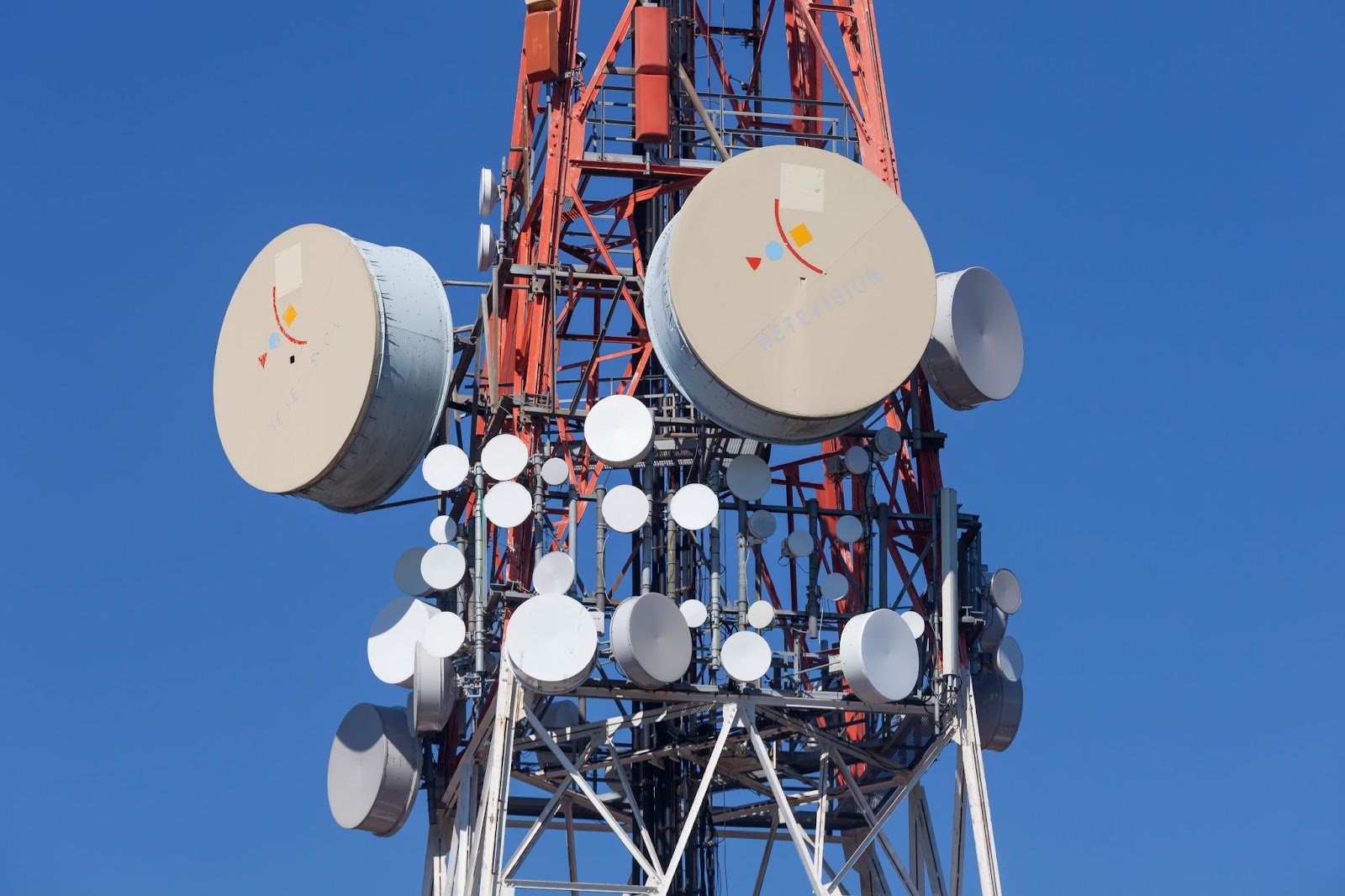
Antenna with AIM distortion
Source: Wikimedia Commons
This type of distortion only occurs in active electronic or RF systems. Hence, it takes two or more frequency signals from an external source or the same approach to merge. As a result, it produces frequency products and multiples.
Indeed, signals from the AIM come with low range power except for a few cases. In such scenarios, it pushes power sufficient enough to alter other receiving signals.
You can find the operations of active intermodulation mostly in modern transmitting appliances. Moreso, the distortion can even get more robust. How? If the manufacturer fails to build it to work around certain specifications.
So, to limit distortion power levels, a device manufacturer would have to stick to guidelines when it comes to:
- Inter Modulation specs
- Power Output voltage
- Frequency
- And many more
What Are the Sources of Active Inter Modulation (AIM)?
- When there are microscopic impurities in a semiconductor substrate layer, AIM occurs.
- Non-linear active components in RF band signals cause active distortions. Or perhaps you find these non-linear components in electronic systems.
- Active distortion occurs when running a system that shares one antenna with various signal sources. For instance, you can find it in LTE band duplexes that share one antenna to receive and send signals.
- If there’s a poor layout or design within RF modules in devices, you’ll have an AIM.
- When you use substandard components or defective electronic components in a circuit, you’re inviting AIM distortion.
- When a harmonics device, of a wireless transceiver, with one signal source, connects to another frequency band with a similar receiver/transmitter signal. Then, an active intermodulation distortion happens.
- An active antenna that amplifies signal levels is also open to active intermodulation.
- In a scenario where there’s a misalignment of transmission signals, AIM occurs. It also causes signal reflection with other frequency bands.
- If you’ve signal lines closely placed together in a circuit board, you’d likely have crosstalk and active intermodulation.
Passive Intermodulation Distortion (PIM)
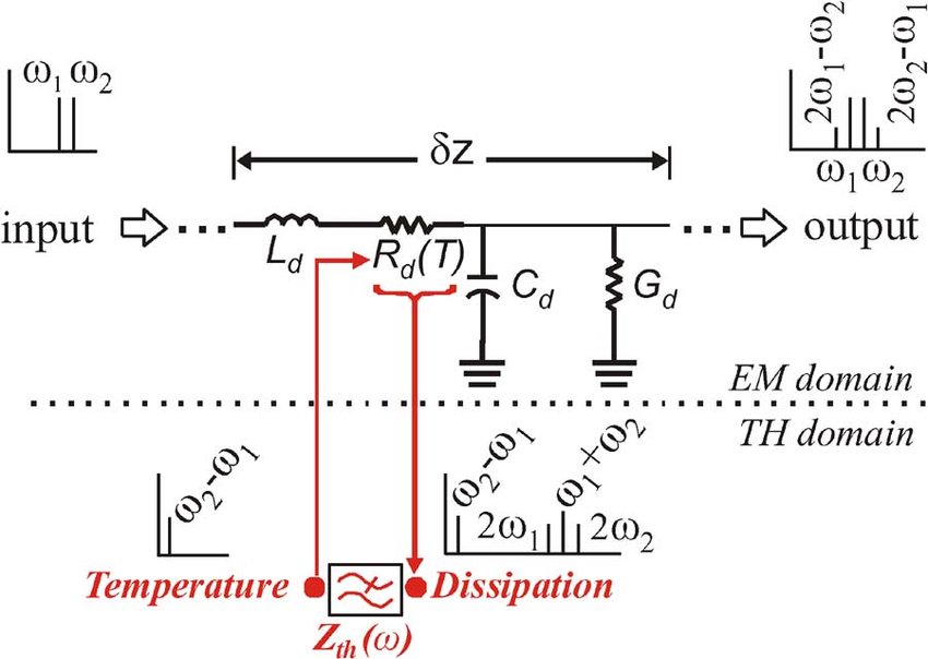
Passive Intermodulation Distortion Diagram
Source: Wikimedia Commons
The distortion type occurs when two more frequency signals are in a passive nonlinear system.
The PIM, as it’s called, produces signals that multiply or add up together to create new passwords. And these signals are similar to the original ones.
Typically, PIM tends to thrive best in elements or systems which operate linearly. In other words, passive intermodulation happens when there’s a deceptive series of non-linearities.
Also, the PIM products have input signal frequencies with harmonics that combine to produce appliances. And these appliances stay within a specific operational band.
What Are the Sources of Passive Intermodulation (PIM)?
- Rusty RF adaptors, connectors, or exposed signal junctions can cause passive intermodulation.
- Do you run RF cables with loose contact connectors? If yes, you’re at the risk of experiencing passive intermodulation.
- If your RF cables don’t have the proper shielding, you’ll have a PIM system.
- Large feeder lines and metal frames also have a high chance of getting passive intermodulation.
- Do you experience spark discharges in your connector sometimes? Then, the connector is most likely prone to oxidation, which leads to passive intermodulation distortion.
- Mechanical switches with poor quality contacts are open to PIM.
- Because of the magnetic hysteresis force, ferromagnetic materials with non-linear systems could easily have PIM.
- Radiofrequency waves hitting a non-linear passive component can cause passive intermodulation distortion.
- Anodic effects like water or moisture on a non-linear appliance can lead to passive modulation distortion.
- Connections with dirt compounds on the connectors or cables can cause PIM.
How Does Inter modulation Distortion Work?
Intermodulation distortion has a similar measurement and representation to the total harmonic distortion. Hence, you can measure it as the percentage of the overall output signal produced.
In more precise terms, intermodulation happens when a mix of signals is in a nonlinear amplifier. The tones of the amplifier react together to create altered or reformed amplitudes. As a result, the combination produces new sideband frequencies—which weren’t available in the original signals.
Now, these sidebands are usually objectionable and non-harmonic because of their nature.
For instance, let’s say a wireless transceiver pushes out a frequency of 440dB. Then, the harmonic frequencies of the device happen at 880dB, 1760dB, 1220dB, etc.
So, something interesting will happen if you combine the wireless transceiver of 440dB with a non-harmonic frequency (for a signal repeater) of 460dB.
Both signal frequencies will combine to produce a third frequency of 900dB (440dB + 460dB). So, the 900dB represents the intermodulation distortion in such a scenario because it’s the sum or difference of two harmonic RF signals.
Why Is Inter modulation Distortion Important?
When we have a higher level of distortion, there will be more interruption to wireless devices.
We’ve seen a surge of wireless transmitting systems for various modern devices in recent times. In modern telecoms, we use a broader frequency spectrum for transmitting wireless signals.
So, the awareness of intermodulation distortion makes network engineers take preventive measures. Plus, passing an IMD test is one feature that certifies an amplifier for specific uses. That way, network engineers can pay more attention to tracking and eliminating it for stable network performance.
Inter Modulation Distortion–How to Avoid Intermodulation Distortion
In truth, you have a higher chance of introducing harmful intermodulation signals when there are many nonlinear devices, like diodes and amplifiers, in your network system.
So, it’s ideal for reducing the number of such nonlinear devices in your signal path. Moreover, you can also do the following:
- Utilize power amplifiers in a linear network system.
- Ensure only to use high-quality components.
- Don’t use non-linear active appliances in your network designs.
- Stay away from substandard signal adaptors and mechanical switches.
- Always shield the circuits of your transmitting devices properly. That way, you can quickly eliminate distortion from external sources.
- Avoid using low-quality signal joints and cable assemblies.
- Always make sure you run a solid connection between couplers, splitters, etc.
- Ensure quality impedance matching between antennas and power amplifiers. By doing so, you’ll be eliminating signal reflections and IMD levels.
- Limit the number of components in a system to avoid intermodulation distortion.
- Keep your receiving and transmitting antenna apart to reduce distortion levels.
- Use ONLY high-quality appliances for your circuit boards.
- Use every component and device for the recommended network range. That way, you’ll enjoy the maximum output and reduce distortion.
Final Thoughts
IMD and its relationship to frequency coordination are crucial parts of the proper wireless
If you plan to have an efficient wireless configuration and deserved expansion, it’s vital to pay attention to the relationship between IMD and frequency coordination. And that’s because they are inseparable.
Hence, it’s best to adopt the instructions we’ve mentioned above to avoid intermodulation when implementing or optimizing a network.
But if you’re still confused about this subject, feel free to reach us. Also, we can provide high-quality rf cables for your wireless plan.