
Yagi Antenna
Source: Wikimedia Commons
You can transmit significant signals with good antenna performance. Gain is one of the most common measurements stated on antenna specification sheets. It plays a crucial role in predicting the performance of an antenna. Then how can we make an antenna gain measurement?
This article will discuss antenna gain comprehensively and show you how to carry out the correct measurements.
Table of Contents
- How to show the Antenna Gain
- What is Antenna Gain?
- Methods of Antenna Gain Measurement
- How To Measure Antenna Gain – Gain Transfer Method
- Wrapping Up
How to show the Antenna Gain
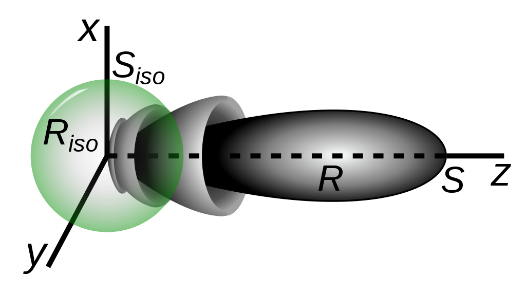
Antenna Gain Pattern
Source: Wikimedia Commons
One of the essential features of antennas is the direction of power propagation. And you can represent a gain in a radiation pattern of a two-dimensional plot. You’ll find the plot’s radius on the decibel scale with this. Also, you can normalize the plot’s radius to the maximum value for an isotropic radiator or a specific antenna.
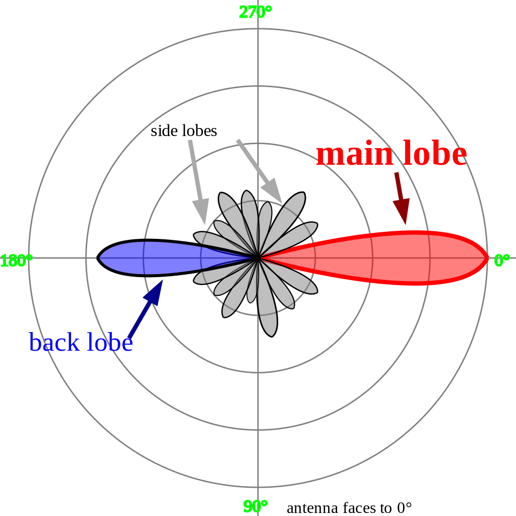
Antenna’s Main Lobe diagram
Source: Wikimedia Commons
The main lobe is usually found in the area with the most power. And opposite it, you’ll find the back lobe. Hence, the sidelobes are the other parts with unintended and redundant radiation characteristics.
So, if you don’t specify the direction, the gain will be the peak value in the antenna’s main lobe direction. For instance, your collinear antenna aligns north-south with 5.41dBd increase.
Consequently, your antenna will receive or transmit more than three times the signal power of an ideal dipole antenna (in the north-south direction). Also, a minute signal will transfer in the east-west course.
What is a higher gain? It refers to the concentration of signal over a lesser beamwidth. And it’s perfect for applications that elude external interfering signals. Also, it’s ideal for some linear applications like those that need to separate a particular signal.
But you need to connect many receiving units, and a wider beam is the best bet. That said, we have various types of antennas. And each of them has different patterns.
Dipole
Dipole Antenna Standing Waves
Source: Wikimedia Commons
This antenna is one of the simplest. It features two straight wires that align on the same axis. Plus, it has a balanced feedline that links to the adjacent ends. That said, when this antenna is by itself, it’s close to omnidirectional.
And it has almost uniform power transmission in all directions. Besides VHF transmissions, you can also use this antenna as FM broadcast receivers and shortwave applications.
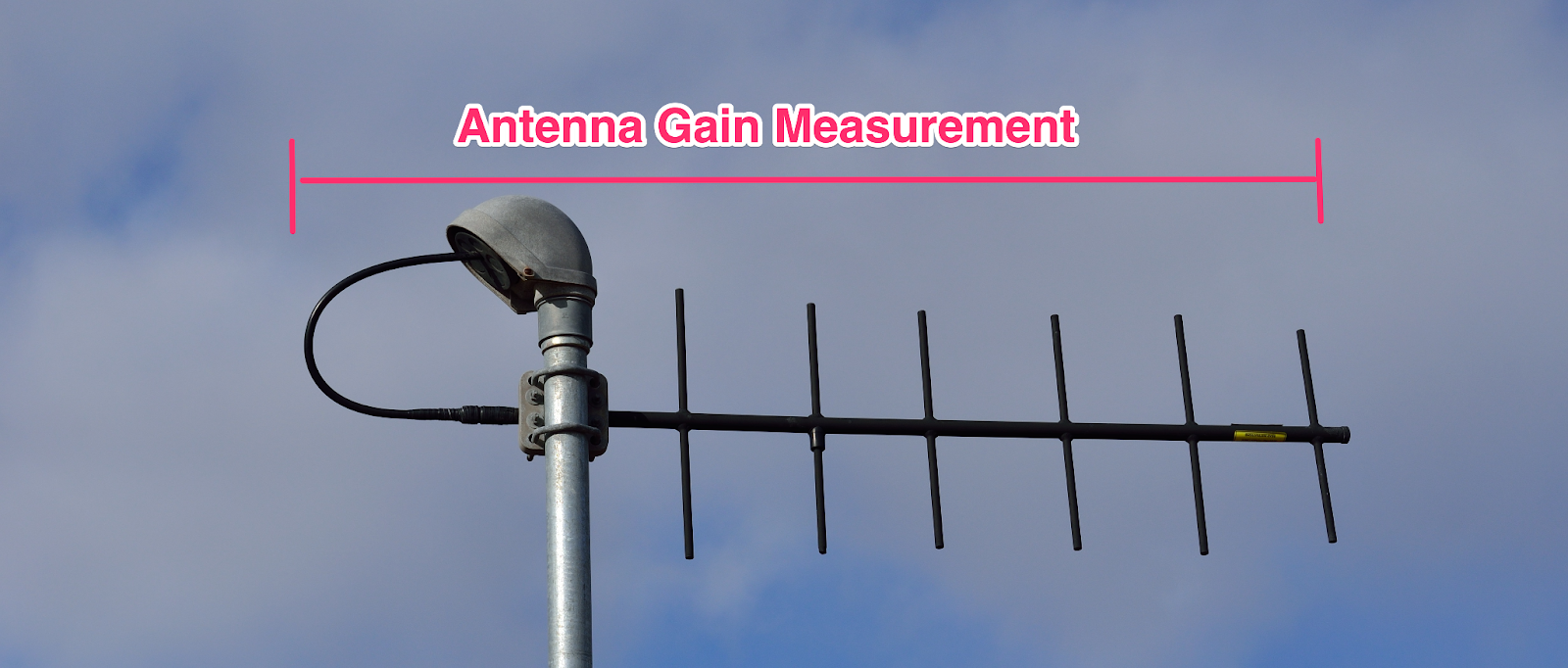
Yagi (or Yagi-Uda)
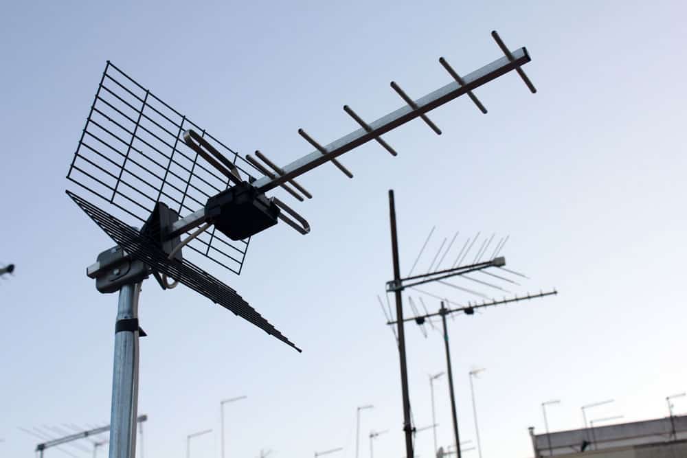
UHF Yagi Antenna
The Yagi-Uda antenna combines dipole elements. So, it receives a signal with one dipole. And the other factors help to return or change the course of energy in a preferred direction.
In addition, Yagi antennas are directional. Hence, it’s crucial to mount it facing the planned signal path.
Furthermore, the Yagi antenna has a wide main lobe with a smaller back lobe. So, based on your preferred signal polarization, you can mount the Yagi vertically or horizontally. Plus, these antennas are best-suited for multipoint or point-to-point applications.
Collinear
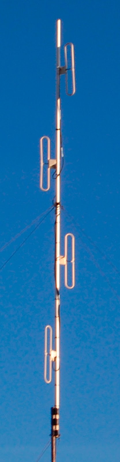
Collinear Antenna
Source: Wikimedia Commons
The collinear antenna combines a series of dipoles. And each of them assembles end to end. Also, they have up to 10dBd alongside many side lobes and narrow bandwidth. So, you can use them in mobile communications.
What is Antenna Gain?
In simple terms, antenna gain means the ability to either direct the radiated power of the antenna in a specific direction or efficiently receive the incoming power from a particular direction. The formal definition of antenna gain is antenna efficiency plus directivity.
Antenna gain is the ratio of maximum radiation intensity of the test antenna to that of the reference antenna, where the input power is the same.
i.e., Gain = Maximum radiation intensity of test antenna
The maximum radiation intensity of reference antenna
And antenna directivity is the ratio of the highest radiation intensity to the ideal isotropic antenna’s average radiation intensity.
i.e., Directivity = Maximum radiation intensity
Average radiation intensity
You can see, in directivity measurement, comparison between two antennas is not taken into consideration. So, the gain of an antenna concerning an isotropic antenna:
G0 = αD
Where:
G0 – an isotropic antenna’s gain
α – a constant that expresses the effectiveness ratio whose value is between 0 and 1
D – the directivity
That said, it’s vital to note that the losses of high-frequency antennas are negligible. Hence, it has an efficiency of 100%. And if α = 1, it means that the value of your measured gain is almost equal to the directivity.
In addition, you can measure the gain in dBi (decibels-isotropic)—if you’re comparing an ideal antenna receiving or radiating energy evenly in all directions.
Also, you can measure your gain in dBd (decibels-isotropic)—if you’re comparing an ideal lossless half-wave dipole antenna (that has 2.15 dB gain).
That said, it’s vital to note that dB is a logarithmic unit. So, if you have 5dB, it’s almost three times the reference power. And 6dB is about four times the reference power, etc.
Methods of Antenna Gain Measurement
There are different ways you can measure your antenna gain. And we classified the methods based on the frequency of operation.
For instance, if your antenna works above 1 GHz, you can measure its gain by free space ranges. But if you have a low frequency (0.1 to 1 GHz), the wavelength tends to be longer. So, it’s not feasible to achieve free space ranges. Hence, you can use ground reflection ranges.
That said, we have two standard methods for antenna gain measurement based on the two specified ranges:
- Direct comparison or Gain transfer method
- Absolute Gain method
When you have a free space range, you’ll notice suppression of the surrounding environment’s contributions. But the reflection ranges, on the other hand, produce constructive interference. And it does this in the practical antenna’s region.
Direct Comparison Method
The direct comparison method is possible when you’re comparing two antennas. You can start by comparing the signal strengths of two things. They include the standard and unknown gain antenna.
That said, it’s crucial to note that the standard gain antenna usually has a known gain. Also, you can form the primary antenna by combining the standard and test antenna. As for the secondary antenna, you can connect the unknown gain and arbitrary transmitting antenna.
Further, the best way to prevent interaction or coupling is to maintain a vast distance. And the space is between the test and standard antenna. That said, you can use an electromagnetic horn antenna for your standard gain antenna.
In addition, the distance you need for the arrangement is r≥2d2/ λ. With that in mind, you should also ensure proper distance maintenance between the antennas (secondary and primary).
When your antennas (test and standard) act as a unit, your load must match correctly. And you can do this by putting an attenuator pad at the receiver input. While you’re at it, it’s pertinent to note that you should experience frequency fluctuation.
The frequency in question is the power spreading towards the primary antenna. Hence, you can achieve this by using a power bridge at the transmitter.
With that in mind, you also need to determine the unknown gain through this method. How do you go about that? Follow the steps below:
Steps
1. Get a switch, S. Then, connect the standard antenna alongside a known gain to the receiver you’re controlling. While you’re at it, ensure that your connection goes an antenna’s the secondary antenna’s (transmitting antenna) maximum signal intensity.
2. Ensure that you apply input to the transmitting antenna. In the pro receivers note of the receiver’s reading. Also, pay attention to the power bridge (P1) and attenuator dial (W1) lessons.
3. You can detach the switch from the standard antenna at this point. But the switch connection will still have the test antenna and receiver. So, to get similar readings on your receiver like the standard antenna, adjust your attenuator dial reading. Then, ensure that your power bridge and dial setting reading is P2 and W2, respectively.
As a result you’l the steps above, you’ll get two Instances:
Instance 1: if P1 is eantenna’s2, your test antenna’s gain will be:
GP = W2/W1
So, in decibels, you can express the equation as: GP (dB) = W2 (dB) – W1 (dB)
Instance 2: if P1 is not equal to P2, your test antenna’s gain will be the product of P1/ P2. Hence, let
P = P1/ P2
10 log P1/ P2 = P(dB)
Then power gain is:
G = GP x P1/ P2
So, when you substitute the value of GP, you’ll have:
G = W2 / W1 x P1 / P2
G = GP x P
In decibels:
G (dB) = GP (dB) + P (dB)
G (dB) = W2 (dB) – W1 (dB) + P (dB)—(gain of the test antenna)
Absolute Gain method
Since the standard gain antenna has calibration, we can calibrate the gain with arbitrary antennas (two or three).
So, we can use distance c to divide the receiving and transmitting antennas. And use (Pr and Pt) to represent received and shared power. Also, you can use Aer and Aet to show the actual apertures of the receiving and transmitting antenna.
If the antennas are similar:
Aer = Aet = G0λ2/ 4π
Based on Frii’s transmission equation, you should have:
Pr /Pt = ( AerAet. )/λ2c2 = (G0 λ2)/4π (G0 λ2)/4π 1/λ2c2
Pr /Pt = (G0 λ)2/4πc
√Pr/Pt = G0 λ/4πc
G0 = 4πc/ λ√Pr/Pt
With this equation, you can also measure the gain of the antenna. And the equ there’ shows that there’s a measurement for the transmitter and receiver.
How To Measure Antenna Gain – Gain Transfer Method
- Power meter and signal generator
- Scalar or vector network analyzer
- Spectrum analyzer with a tracking generator
That said, we’ll use the network analyzer for two reasons. we’ll, the network analyzer has a source and receiver. Second, it’s convenient and easy to use. Here are some integuments you can use to measure the antenna gain:
lets that in mind, let’s proceed to the steps:
1. Laun” h the “don’t care.” Then, place your reference antenna on a balanced holder.
2. Ensure that your antennas have a far-field distance.
3. Pr “don’t lie “k your “don’t can analyzer’s network analyzer’s transmitter (port 1). And relate your reference antenna to the receiver (port 2).
4. Make sure your antennas orient (based on the direction of maximum radiation intensity and polarization).
5. Trigger your S21 measurement.
6. program your preferred frequency range on your instrument (network analyzer).
7. Enhance your dynamic range.
8. Execute your response calibration. Consequently, you should have a flat S21 response. The response is visible at the 0 dB—across a particular frequency range. Hence, it means tan tenna’s reference antenna’s gain is expected.
9. Next, use the AUT to replace your life you’re a ten. While you’re at it, do the replacement at the actual position.
10. Write down the new values of the S21. The result is the loss or gain of the AUT in connection with the reference antenna (relative).
So, you can get the AUT’s gain with the equation below:
RAUT = RRef + RRelative
Recommendations
1. You can opt for similar antennas for your R “don’t ant’s a and “don’t you’ll Consequently, you’ll find it easier to match and position the antennas.
2. Place the REF and AUTyou’reto back. While you’re at it, ensure that you can swivel them at 1800.
3. You can reduce ground reflection by measuring with the absorbers under the antenna.
Wrapping Up
In closing, antenna gain measurement is necessary to gain a successful and effective transmission. Do you need assistance in calculating your antenna gain? Please, feel free to reach us. Also, we provide cable assemblies for your antenna system.