
You might not know antenna systems are working, but you have used them in every form of wireless communication. What is an Antenna, though?
The Antenna can transmit Radio as well as microwave signals.
Thus, it is a conducting and resonating device that operates on narrow frequency bandwidth. If you are ever a little bit into wireless communication engineering, learning this concept will help you.
Table of Contents
- How Does an Antenna Work?
- Types of Antenna
- What is the Polar Diagram of an Antenna?
- What are Antenna Connectors?
- Key Classes of Antenna Connectors
- Conclusion
How Does an Antenna Work?
The primary responsibility of an antenna is to collect or remit electromagnetic radiation in space. Moreover, electromagnetic waves are converted into electric signals or vice versa.
Here, the Antenna receives a signal from the guiding device or transmission point like a coaxial cable. The received charges move at a certain velocity to create electromagnetic waves in the machine. Thus, the device converts the electrical signal into an electromagnetic wave and transmits it into free space.
Reception Antennas oppositely do the task. They catch electromagnetic waves. When charged particles move, they also disturb the electrical field, thus developing currents. So, the Antenna passes the electric signal through a coaxial cable to your intended devices such as television, etc.
Applications
There are many areas where you will see the applications of Antennae. It is because antennas help communicate data in places where any other medium is impossible. Some of them are
- Flight Systems, where the pilot must constantly communicate with the ground staff. Since you cannot tie a cable up to a plane, you can use microwave signals to make the connection.
- TV and Radio, where you want to catch up on various channels.
- Internet Connection, where you connect to the Wi-Fi signals using the Antenna embedded in your phone
Types of Antenna
According to the functionality and shape of the antennas, we can classify the equipment into the following types.
Yagi-Uda
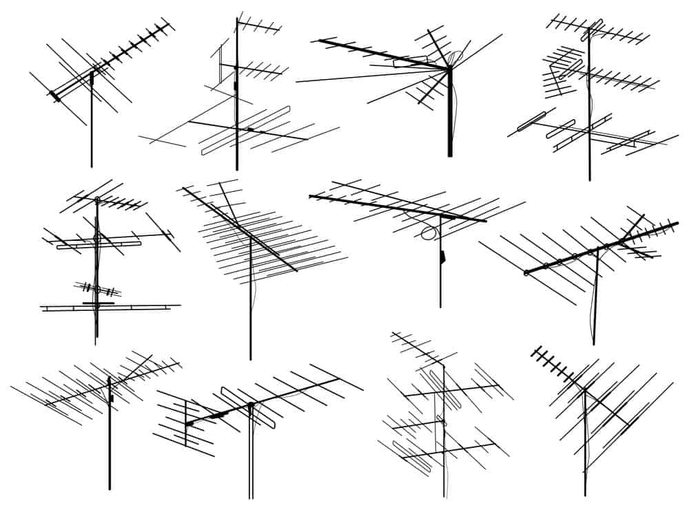
Yagi UDA is the most common type of Antenna that you may have seen in the old TVs and Radios around your house. To explain, Yagi is a directional antenna containing half-wave dipoles, all set in parallel positions. Thus, it boosts the reception quality and acts as a bridge in TV and global satellite systems.
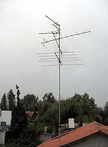
Caption: A typical Yagi-Uda Television Antenna
Source: https://en.wikipedia.org/
Aperture
The aperture antennas are equipment capable of transmitting energy in all directions. It has an opened part in front of the Antenna, known as the Aperture.
Additionally, the antenna power beam emitted through the Aperture can be more substantial than a typical two-way transmission wire.
As for the application, you may have seen them in the form of surface search radars and microwave equipment. Also, the Horn antenna is one of its well-known examples.
Caption: Aperture Antenna
Reflector
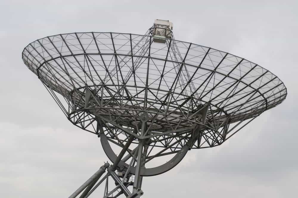
Reflector antennas are systems having reflective surfaces. These types of antenna systems can transmit as well as absorb electromagnetic power waves. You usually see the reflectors in satellite communication devices and remote sensors. Corner and Parabolic Reflecting Antennas are typical examples of the stated kind.

Caption: Reflector Antenna
Wire
It is the type of Antenna made up of a long wire. So, in a wire antenna, you use an antenna cable to connect the transmitter or a receiver through a tuner. Here, a tune catcher helps catch the signals according to a specific wavelength.
Since wire antennas are easy to install, many cable operators use them for more precise TV signals. A typical example of a wire antenna is the Dipole, Helix, and Monopole antennae.
Caption: Wire Antenna
Lens
Lens antenna has an electromagnetic lens embedded on the surface. Consequently, you use the converging and diverging properties for receiving and transmitting a strong signal. Furthermore, the lens size you will use is inversely proportional to the frequency of the movements.
Usually, a dipole antenna has a lens fixed on the surface. Therefore, signals are converged at the focal point of the lens, and you get high frequency, good bandwidth signals. The lens antenna can be further classified into two more kinds.
- Dielectric Lens Antenna
- Metal Plate Antenna

Caption: Lens Antenna
What is the Polar Diagram of an Antenna?
You can graphically represent an antenna’s radiations with the help of related variables. Also, the variables can include the field strength at a specific radius, the power per unit solid angle, and sometimes the directive gain.
In plotting the relative amplitude, you can use either the linear scale or the dB measures. Hence, it will describe the power field at different angles on the horizontal or vertical planes.
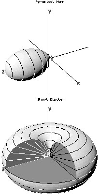
Caption: Three-Dimensional Antenna Radiation Pattern
Source: https://wikipedia.org/
What are Antenna Connectors?
The antenna connector is the radio frequency regulator fixed at the ending terminal of an antenna. It helps solve the problems of the boosted signals, such as discontinuity, impedance problems, and energy loss. However, in case of any loss, the antenna connector will be held responsible and changed immediately.
Although in an antenna assembling process, the connectors are not as necessary as the Antenna itself. Yet without investing in a suitable connector, your advanced antenna workspace is useless.
The structure of an antenna connector is also fundamental. Depending on where you will mount the Antenna, the antenna manufacturers have to determine the size and caliber of the connecting pin. Hence, poorly selected and fixed connectors will reduce the system’s efficiency.
Key Classes of Antenna Connectors
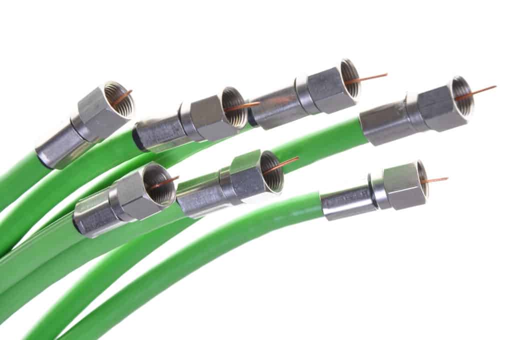
Caption: Different Antenna Connectors
Here are some significant classes of antenna connectors that you can use depending on your needs.
SMA connector
The SMA or Sub Miniature Type-A connectors are highly accurate and use semi-precision threads inside connection terminals. Thus, you can use it when you need a reliable connection medium for varying frequency measures.
The connector comprises a 5/16-inch hex nut on the male side. At the same time, the female counterpart contains externalized threads and a mating receptacle interface. By joining both sides, you can establish the transfer of signals.
The main features are
- Frequency of up to 18GHz
- The impedance of 50 OHMS
- Voltage rating up to 500 Volts
- VSWR of 1.15+0.1f
- Radio Frequency Leakage of up to 90dB per minute at a frequency range of 2-3 GHz
Popular applications of such connectors are in cellular networking, GPS antennas, and Wi-Fi antenna.
RP-SMA connector
A simple variant of the SMA connector, the RP-SMA reverses the matting interfaces of the connector, thus having Reverse Polarization. However, it looks like the SMA connector performs similarly.
The RP-SMA has threaded connectors that mate when they are screwed together. Also, these are made with the same material and support similar ranges of applications. The main features of an RP-SMA connector are
- Frequency of up to 18GHz
- The impedance of 50 OHMS
- Voltage rating up to 500 Volts
- VSWR of 1.15+0.1f
- Radio Frequency Leakage of up to 90dB per minute at a frequency range of 2-3 GHz
Primarily, the RP-SMA connector works to prevent the public from using high-gain, professional antennas. So, they are easily used as a replacement for the Antenna of choice.
N-type connector
N-Type connectors are efficient and perform well over 50-75 ohms. Moreover, it accommodates every variety of coaxial cables, making it a choice for a larger audience.
Like the above types, the N-type also follows the same mating interfaces. It has a male side connector with a center pin, and the female side has a receptacle. Hence you can make the connection by fixing them with each other via a hex nut. It features
- Frequency of up to 11GHz
- The impedance of 50 to 75 OHMS
- Voltage rating up to 1500 Volts
- VSWR of 1.3f
- Radio Frequency Leakage of up to 90dB per minute
Furthermore, Type-N connectors are used on base stations of satellites and in the industrial environment.
MMCX connector
The Micro-Miniature Coaxial connector is a small connector that can rotate 360 degrees about the connection. Typically, they are made up of brass, gold, and copper plating. The design is the same as the above connectors, i.e., Male and Female mating connection sides.
It features
- Frequency of up to 6GHz
- The impedance of 50 OHMS
- Voltage rating up to 170 Volts
- VSWR of 1.25f
- Radio Frequency Leakage of up to 60dB per minute at a frequency range of 2-3 GHz
The size of MMCX connectors has made it easier for many devices to incorporate wireless connectivity in their systems. Also, you can fit them where you need lighter components. Still, it will deliver you a robust performance.
TNC connector
It is an extended version of BNC connectors that support microwave frequency ranges. Moreover, the structure is fabricated according to the standards and has half an inch diameter. The antenna manufacturer uses material that is typically brass insulated with PFTE.
Additionally, the composition is based on males and females. Also, connectors carry 7/16-28 threads internalized on the male and externalized by the female. Basic features are
- Frequency of up to 11 GHz
- The impedance of 50 to 75 OHMS. Commercially available versions usually have 50 OHMS.
- Voltage rating up to 500 Volts
- VSWR of 1.35
- Radio Frequency Leakage of up to 55 to 60dB per minute, depending on the impedance.
TNC connectors secure mating to various wireless networking systems. Also, you can apply them at the terminating ends of different coaxial cables.
RP-TNC connector
Reverse TNC connectors work the same as TNC. But the genders are reversed, making it unable to make connections. Here the female side contains the connecting pin and reverses the polarization process. It can support
- Frequency of up to 11 GHz
- The impedance of 50 to 75 OHMS. Commercially available versions usually have 50 OHMS.
- Voltage rating up to 500 Volts
- VSWR of 1.35
- Radio Frequency Leakage of up to 55 to 60dB per minute, depending on the impedance.
RPTNC connectors are found on Radars, cellular networking systems, Basestations, etc., to limit amateur attachments.
U.fl connector
The U.fl connector uses the internal Antenna of the attached devices, and it has a small mounting area so that you can adjust it to the smallest spaces.
The connectors comprise a phosphor bronze shell and liquid crystal polymer insulation.
Additionally, you must be careful while connecting and disconnecting it repeatedly, as it can cause damage to the antenna products.
The U.fl supports
- Frequency of up to 6 GHz
- The impedance of 50 OHMS.
- Voltage rating up to 200 Volts
- VSWR of 1.35
The U.fl is usually embedded on PCBs so several devices can connect wireless. Also, you can pair it up with a larger connector to support extensive connections.
FME connector
FME is an abbreviation of “For Mobile Equipment.” Thus, FME connectors are small threaded connectors embedded in mobile devices. However, you will have to attach a small coax cable to perform the tasks.
It features
- Frequency of up to 4 GHz
- The impedance of 50 OHMS.
- Voltage rating up to 500 Volts
- VSWR of a straight connector is 1.35
Generally, you can install the FME connectors for GPS and Wi-Fiwifi connectivity in the vehicles, and it has an extensive application over broadband devices.
Conclusion
Antennas catch or broadcasts signals in space. However, you may need a compatible antenna connector at the terminal of the devices.
Hence, to choose a suitable antenna, you must consider your needs. Here at Cloom, we offer a wide range of hard-to-find antenna cables for proper connection. For more information, contact us now.