
Although you may have switched to wireless devices, still the primary connection needs wire connections. For that, you may use patch cable wiring or Ethernet cables. Patch cable wires have become a part of our lives for quite some time as it helps to create Ethernet connections.
Since the term “patch-in” means connectivity, this cable patches the signals from one router switch or hub to another router. You can attach the cable from both ends and create a connection between the end device and the power source.
The patch cable is a coaxial cable that may work as Ethernet, yet it is effective on smaller distances. Thus, you can use it to make connections to places like corporate offices, etc.
Patch cable assembly requires some wiring standards to follow. Moreover, you can assemble the wires in two ways, “Straight-through” or “crossover.” Read along to find out more about it.
Table of Contents
- T568A and T568B Wiring Standard Basis
- Common Types of Patch Cord Cables
- Straight Through versus Crossover Cable: When to Use?
- How to make an Ethernet Patch Cable?
- Conclusion
T568A and T568B Wiring Standard Basis
You can use an RJ-45 connector, a modular eight position, eight connector pin plug at the end of the patch cable. The pinout is acceptable on two standards as per ANSI, TIA, and EIA. These two are
- T568A wiring standard
- T568B wiring standard
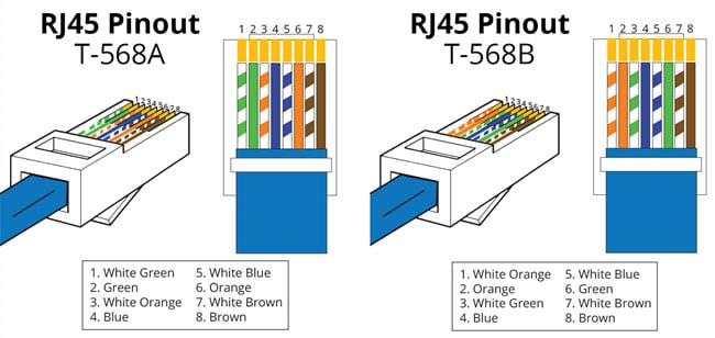
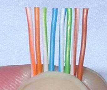
Caption: Cable assembling on T568A and T568B standard
The T568A standard applies that the colored wires must be in the following arrangement, that is
- White Green
- Green
- White Orange
- Blue
- White Blue
- Orange
- White Brown
- Brown
Whereas the T568B standard says that the wire color code must be in this form
- White Orange
- Orange
- White Green
- Blue
- White Blue
- Green
- White Brown
- Brown
The standard bodies have ratified TIA/EIA 568A since 1995. They replaced the standard with 568B, and till now, you have been using the latter. Interestingly, both standards define the internal wiring for unshielded twisted pair cable and RJ45 plug.
Although you may think to use these standards interchangeably, yet it is not the case. Therefore, the measure has its application and is best used under specific circumstances.
Also, if you do not follow the instructions correctly, you may get lost signals in network ports. Thus, you have to arrange the cable assemblies and conform them to the expected standards at your own risk.
Common Types of Patch Cord Cables
There are two main types of standard patch cable, straight through and crossover. Let us look into their difference.
Straight-Through Cable
A straight-through cable is the type of patch cord whose both ends are of the same kind. That is, both the terminals follow the same standards, either T568A or T568B. Thus, the cable does not have to swap the connection along the way.
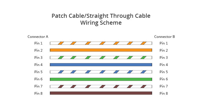
Caption: Straight through cable wiring scheme
Source: https://www.fs.com/
If you want to connect a computer with a network hub, it has to be your choice. Often the patch cables are referred to as straight-through cables, and the local area networks use them for connection. The following figure shows a simple straight-through line, following T568A standards.
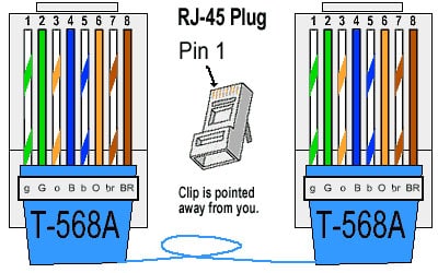
Caption: Straight through wire following T568A standards
Source: https://incentre.net/
Crossover Cable
Unlike straight through, the Ethernet crossover cable uses two different wiring standards at each RJ45 connector end. One will use the T568A, while the other must be using T568B. Otherwise, there will be no difference left in the straight-through and structured crossover cabling.
The wires inside the cable crossover connect the corresponding color on the next side as the wiring arrangement is different. The following figure shows the internal structure of the crossover cable.
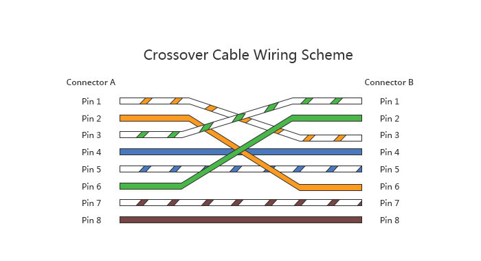
Caption: Crossover cable wiring scheme
Source: https://www.fs.com/
A crossover Ethernet cable is used to connect the computers directly with each other. Moreover, it can connect two routers and two hubs as well.
Straight Through versus Crossover Cable: When to Use?
In short, the crossover wires connect the same type of communicating devices, like computer to computer, hub to hub, or router to a router. Instead, the straight-through fiber patch cable connects two devices like a router to a PC or hub. The following scenarios will help you out understand the logic behind the connection.
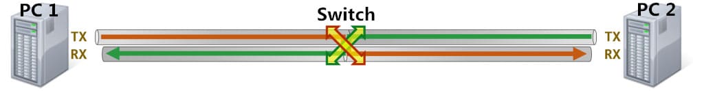
Computer to Computer (Same Devices)

Caption: Transfer from PC to PC
Source: https://www.fs.com/
Usually, you connect two computers to share data from one-two another. When they join, they will find the same path to pass the data. As both PC try to connect with the TX terminal, the signals will collide. In this situation, the passing data could be destroyed or damaged completely. Therefore, you need a crossover cable to switch the paths and use two different pins for data transmission.
Computer to switch to Computer (Different Devices)
Caption: Transfer from PC to switch to PC
Source: https://www.fs.com/
A switch is designed to alternate the data routes between two computers, hence the name “switch.” In this scenario, you can use a simple straight-through cable. The PC will automatically transmit data to TX, which will go to the RX side of the switch and then be passed to the RX of others. Therefore, the straight-through cable does the job correctly.
Computer to Switch to Switch to Computer (Combination)
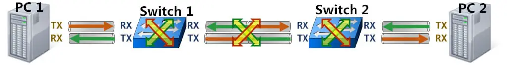
Caption: Transfer from PC to switch to switch to PC
Source: https://www.fs.com/
There can be some cases where you are using both the same and different device connections. To deal with such a system, you can use both cables, crossover or straight through.
As in the picture, you can see the first half has a computer and switch, so you will use straight through to connect them. Next, the middle part has the same devices to pass the signals. Thus, you will require a crossover cable to switch the wire pair. Then comes the switch to the computer part. Here you will use a straight-through line again to connect the patch panel.
How to make an Ethernet Patch Cable?
If you are interested in assembling your patch cable, you must first choose between the Cat5e and Cat6 cables. The main difference between the two will be the bandwidth, and cat6 cables can transfer a large amount of data over a distance. It is a fantastic choice if you use it for large networks in commercial areas or for sharing high-end multimedia.
But, you do not need it in homes or small setups. Instead, you can choose crossover or straight-through wired Cat5e patch cable. Overall, it is a fun experience to create your line for your personal use.
Tools
The tools that you will need are:
- Bulk Cable of Category 5e or Cat5e ( You can use Cat6, depending upon your need)
- Bulk RJ45 Connectors for Cat5E or Cat6
- RJ45 Crimping Tool
- Strain-relief boots
Procedure
The process includes the following steps;
Step 1
First, slip the cable through the strain relief boot. Make sure that the fitted side fixes on the line and the opening is facing you. The use of a strain-relief boot is optional, as it keeps the ethernet connection in place, and no copper cables are poking through the link.
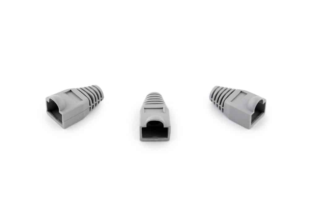
Caption: Strain-relief boots
Step 2
Next, strip the cable jacket on the outside. You will see four pairs of twisted cables. Straighten them out and organize them according to the colors. Be careful about cutting out the actual wires as it will waste them, and you will not connect them with pins.
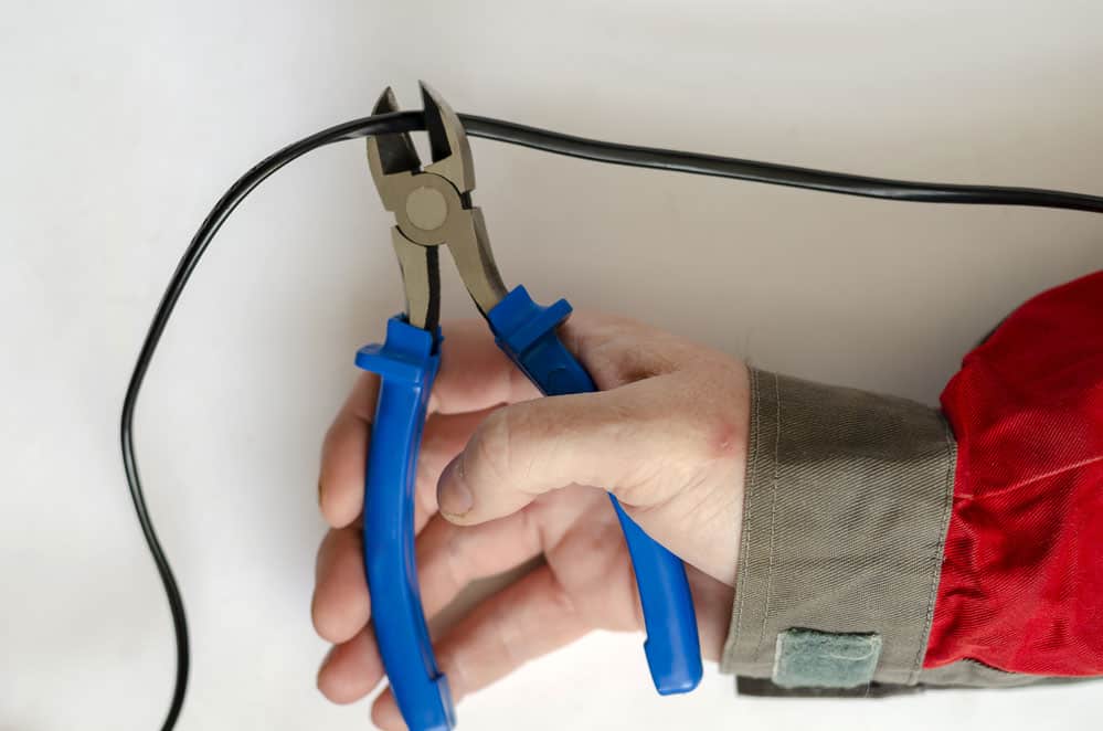
Caption: Clamping the cable jacket
Step 3
Now, order the cables according to the standard you want to follow. If you don’t have any personal choice, you can go for the T568B arrangement as most people do.
Caption: Ordering the wires
Source: https://www.groundcontrol.com/
Step 4
Then, use an insert guide to keep the wire colors arranged. If you don’t have one, you can use your fingers to hold the wires in position. Expose the upper part of the copper cables and slip the RJ45 connector onto it. Make sure that each wire has got into its separate apartment. Without an insert guide, you might achieve it in a few tries.
Step 5
In the end, crimp the connector with the crimping tool. The crimping makes the connector pins meet the thin copper cables of the cable. This way, the individual conductors have a connection and can pass the signal. Press the crimping tool hard so that the wire is pressed correctly. DO it on the other side as well.
And there, you have made your first patch cable successfully. Connect it to a device and check if the connections are all good.
Conclusion
A patch cable connects the devices across small networks, and it has two connecting ends that may or may not follow the same wiring standards. Thus, you need to select the type of cable according to the application area. Also, you can assemble your very own patch cable to cater to your unique needs.
Here at Cloom, we offer help in coaxial cable assemble. Hence, even if you mess up the patch cable wiring, we are here to help you. Contact us and get your problems solved now.