
The best way to wire outlets and switches can be stressful, especially if it is your first electric project.
Moreover, incorrectly wiring them can lead to blown fuses, wrong outlets, or potential electrical hazards. You want to avoid these dangers by using the correct wiring steps.
This article will provide the necessary guidelines to follow to achieve accurate wiring. We will also help you with the best way to wire outlets in different situations.
Table of Contents
- Tools Required
- Step 1: Turn off the breaker
- Step 2: Strip the wire
- Step 3: Bend the wire
- Step 4: Connect neutral to your replacement outlet
- Step 5: Connect the ground wire to the replacement outlet
- Step 6: Connect the live wire to the replacement outlet
- Receptacle Wiring Best Practices
- Wiring multiple outlets in parallel
- Wiring of multiple switched outlets
- Wiring a switch to an outlet
- Wiring a 15A outlet with a light switch
- Wiring a split switch outlet
- Wiring an AFCI and GFCI to the outlet
- Wiring dual outlets from 240V source for 120V
- Wiring a combination of 120V outlet and 240V outlet
- Wiring 20A, 120V outlet
- Wiring 20A, 240V outlet
- Wiring 30A, 240V outlet for dryer
- Wiring 50A, 240V outlet
- Step 7: Secure the receptacle in the box
- Step 8: Install the faceplate
- Conclusion
Tools Required
Before beginning your DIY outlet wiring project, there are vital tools you need to have. Ensuring you have the correct tools gives you the confidence for a successful wiring job.
These tools include the following.
- Drywall saw
- Screwdriver
- Needle nose pliers
- Voltage tester
- Wire cutter/ stripper
- Utility knife
In addition to the tools to use, you will need to have these materials;
- Wire connectors
- Electrical wires
- Remodeling box
- Receptacle/Outlet/Switch
Step 1: Turn off the breaker
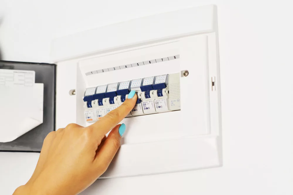
A woman turning off a circuit breaker
Turning off the breaker is the first step to beginning your wiring project.
Using a voltage test on the outlet to ascertain that it is off. If the tester lights up, there is voltage in the outlet.
Another way to test for current is to attach a working light bulb to the wires or old outlet.
The bulb lighting up shows the presence of an electric current flowing.
Once you double-check that the breaker is off and there is no flow of electricity, it’s time to remove the faceplate.
A faceplate is a piece of plastic covering the electric outlet.
Some faceplates have a single screw at the bottom, while others have two screws.
Depending on your outlets, use your screwdriver to unscrew them from the outlet.
After detaching the faceplate, carefully pull the outlet from the electrical box to expose the wires.
Step 2: Strip the wire
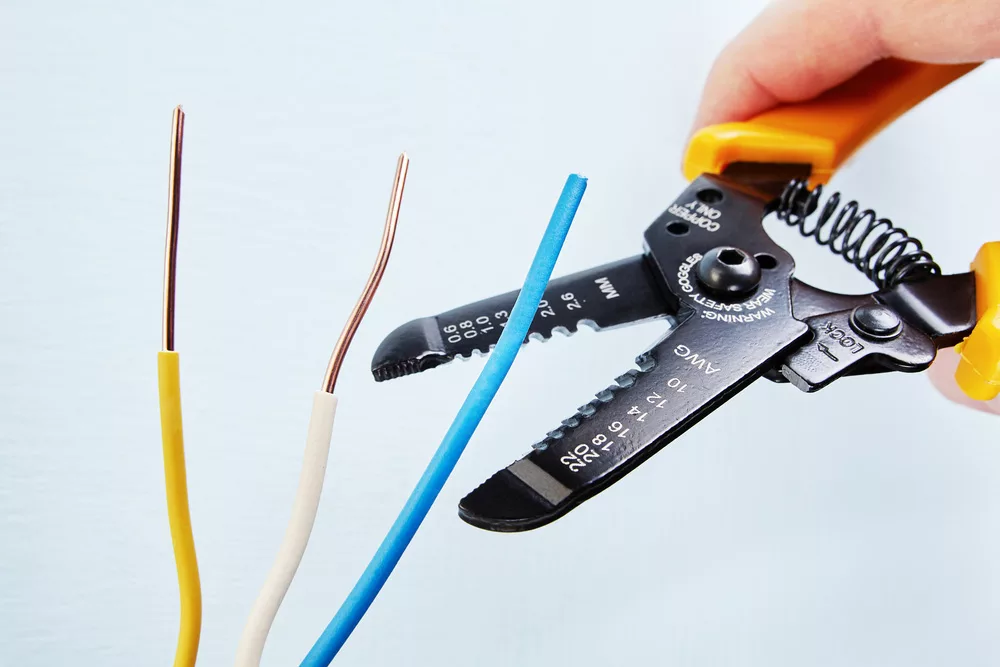
Electrician stripping a wire using a wire stripper
When installing a new receptacle, use the wire stripper or cutter to remove the insulation.
Strip the wire to expose it around three-quarters of an inch or long enough to intertwine in the outlet.
The three wires are the live wire, neutral and ground wire.
If the wires are attached to the terminal, you should unscrew them so they can be free.
Step 3: Bend the wire
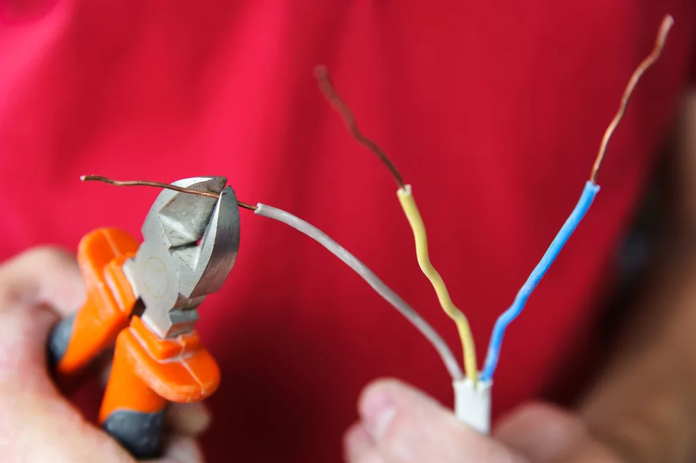
Electrician bending electric wires
Use the needle nose pliers to bend the stripped wires to create a hook shape or u-shape.
However, if the wires attaching to the old outlet are damaged, cut and peel the insulation.
Use the wire cutter or utility knife to cut the damaged part and bend the fresh wire with the nose pliers.
Step 4: Connect neutral to your replacement outlet
Find the neutral wire, which is white, and screw it to the neutral location of the outlet.
Make sure that you have bent the wire so that it screws perfectly. Also, if the bent wire is too long, cut it into a size that will attach tightly to the receptacle.
Use the screwdriver to tighten the silver screw by turning it clockwise to tighten the neutral wire.
Step 5: Connect the ground wire to the replacement outlet
Find the ground wire to tighten it to the outlet with its screw.
The standard color code for the ground wire is green or green with yellow stripes, therefore is easy to find. In some instances, it is bare copper.
Attach the ground wire with the loop you bent earlier on the ground location of the receptacle.
Tighten the wire using the green screw with your screwdriver by turning it clockwise.
Step 6: Connect the live wire to the replacement outlet
Find the live and hot wire sizes, and attach them to the replacement outlet. The live wire is black.
Ensure that you have bent it correctly and place the wire loop on the hot wire location of the outlet.
Securely tighten the golden screw with your screwdriver to ensure the live wire connection with the outlet is sturdy.
Receptacle Wiring Best Practices
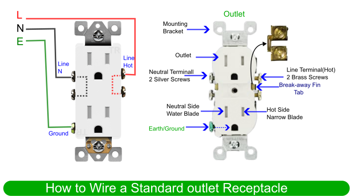
Wiring diagram for a standard outlet receptacle
To wire the outlets in different situations, here is how to handle the wiring correctly.
Wiring multiple outlets in parallel
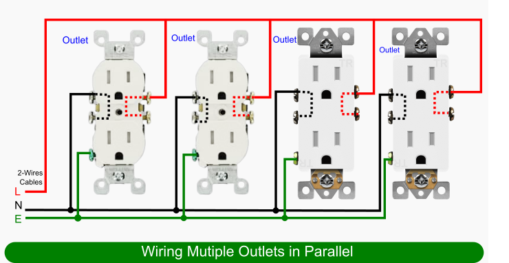
Wiring diagram for multiple outlets in parallel
Splice the wires into a pigtail and connect them to each outlet when connecting more than one outlet in parallel.
Each outlet is independent, and you connect them in separate cables.
Wiring of multiple switched outlets

Wiring diagram of multiple switched outlets
Connect the switch to the live wire. The switch will serve the other outlets in a parallel connection.
You can use the switch to control it on and off.
Wiring a switch to an outlet
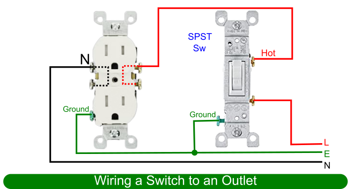
Wiring diagram of a switch to an outlet
Remove the hot wire from the outlet brass terminal and connect it to the first terminal of the switch.
Connect the second terminal to the brass terminal of the outlet.
Use the switch to control the on and off connection.
Wiring a 15A outlet with a light switch

Wiring diagram of a 15A outlet with a light switch
You can add a light switch to an already existing outlet. Here are the steps.
Wire the hot outlet terminal to the first switch terminal.
Connect the second switch to the lighting point.
Connect the neutral wire to the light bulb.
Wiring a split switch outlet

Wiring diagram of a split switch outlet
In this setup, you split the outlet connection into upper and lower portions.
The switch controls the upper part while the lower part always remains life.
Here is how you achieve the connection.
It would be best to connect the live wire to the first switch’s terminal, and the switch’s lower live terminal.
Wire the switch’s second live terminal to the switch’s upper live terminal.
Wiring an AFCI and GFCI to the outlet

Wiring diagram of an AFCI and GFCI to the outlet
This series connection only applies to AFCI and GFCI connections to an outlet.
Connect the outlet to the GFCI load terminal that is connected to the AFCI load terminal.
The AFCI and GFCI will control the standard outlets.
GFCI and AFCI will work as a single unit rather than using two outlets in the connection.
Wiring dual outlets from 240V source for 120V
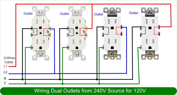
Wiring diagram of dual outlets from 240V source for 120V
Wire the first and third live outlet terminals to the second line and the second and fourth live outlet terminals to the first line.
Join the circuit breaker’s neutral wire to all neural terminals of the other outlets.
This setup lets you connect dual outlets to a single 240V line to supply 120V to other appliances.
Wiring a combination of 120V outlet and 240V outlet
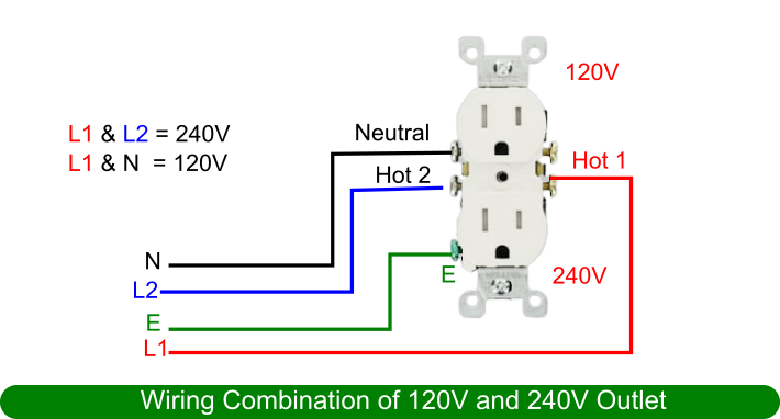
Wiring diagram for a combination of 120V outlet and 240V outlet
You will split the connections into upper and lower portions of this wiring setup. The upper portion provides 120V while the lower portion supplies 240V.
To achieve this connection correctly, wire the first and second lines to the live terminals of the lower outlets.
Join the neutral and ground wire to their respective neutral and ground terminals.
Wiring 20A, 120V outlet

Wiring diagram of a 20A, 120V outlet
Connect the 20A 120V receptacle to a 120V supply through the live, neutral, and ground wires.
Wiring 20A, 240V outlet
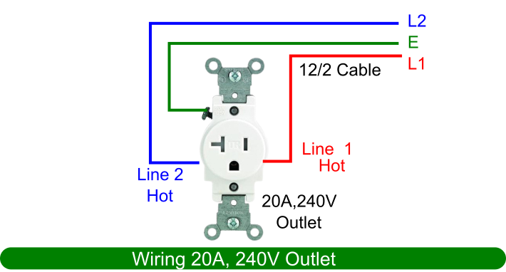
Wiring diagram of a 20A, 240V outlet
The neutral is not necessary for 240V wire setups. Connect line 1 and line 2 to the brass terminals of the outlet.
Connect the ground wires to the ground terminal.
Wiring 30A, 240V outlet for dryer
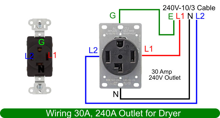
Wiring diagram of a 30A, 240V outlet for dryer
To wire an outlet for the dryer, the neutral is necessary.
Use a 10-gauge 3-wire cable from a separate breaker to connect the first, second, neutral, and ground wires to the outlet.
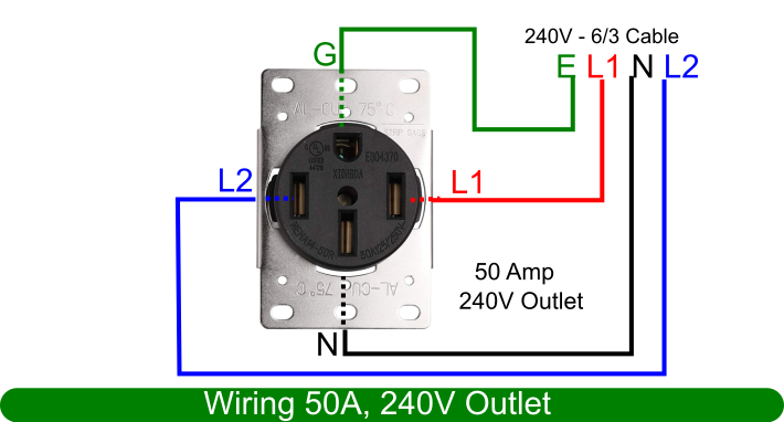
Wiring 50A, 240V outlet
Wiring diagram of multiple switched outlets
Use a six gauge three wire cable from separate circuit breakers since it is a high load and amperage setup.
Connect the line 1, line 2, neutral and ground terminals to the relative first live, second live, neutral, and ground terminals.
Step 7: Secure the receptacle in the box

Electrical wires in a box
Fit the wires in the electric box and use mounting screws to screw the top and bottom of the outlet to the box.
Step 8: Install the faceplate
Place the faceplate on the outlet and covet it securely with its screws.
Once the outlet is secure in the wall, turn on the breaker.
Test with a voltage tester to see if the outlet is functioning correctly.
You should see it light up with a voltage reading on the voltmeter.
If the outlet is not functioning, and you believe you have everything the right way, you should call an electrician.
The professional should be qualified to diagnose and solve the issue.
Conclusion
Handling your first electrical projects, such as wiring switches and receptacles, should be manageable.
To summarize, this guide helps you to learn the best way to wire outlets.