
Can you make your own HDMI cable? Every good thing ends someday; the same is true with HDMI cables. Due to continuous wearing and tearing, the cables get damaged over time. Once damaged, you have three options:
- To buy a new one
- To repair the existing one
- To build a new cable by yourself.
This article discusses all about making your own HDMI cable. Let’s get started.
Table of Contents
- How are HDMI cables made?
- Are all HDMI cables the same?
- How to make HDMI cables yourself?
- Conclusion:
How are HDMI cables made?
Different factories use different procedures to make an HDMI cable; however, you have to follow a standard procedure, including the following steps:
- First, cut the cable with a wire-cutting machine and strip it with an automatic stripping machine.
- Trim the aluminum foil with an aluminum trimming tool.
- Position the inner wire on the plastic wire holder. Factories use an angle-type traverse for this purpose.
- Strip the inner wire with a stripping machine.
- Tin the wire.
- Assemble the wire with the connector.
- Attach the connector to the cable through welding.
- Fix the connector at its place using the molding mechanism.
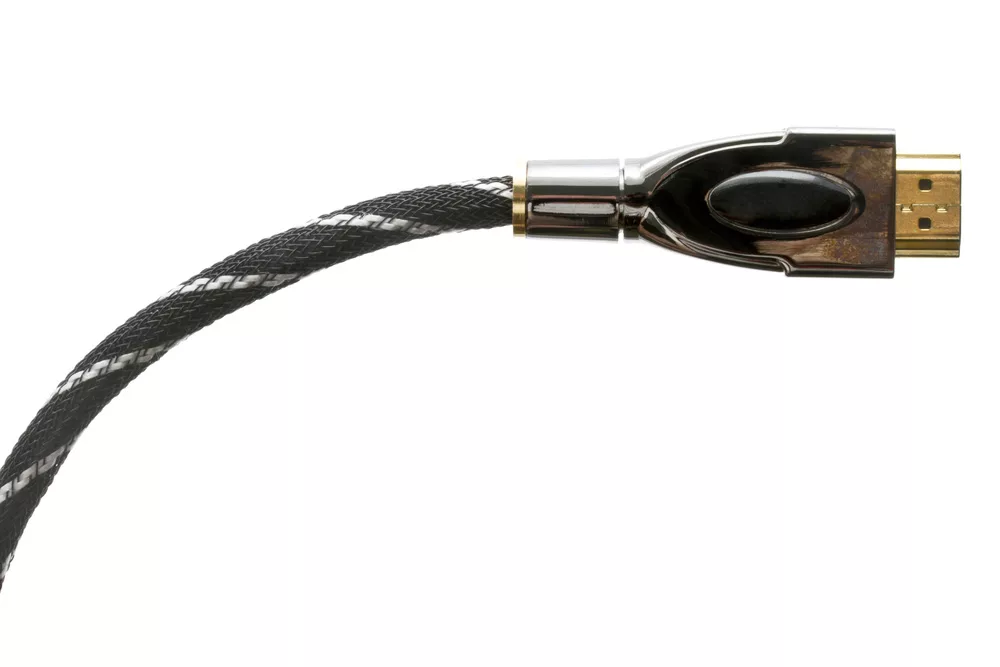
Braided HDMI cables
Are all HDMI cables the same?
All HDMI cables may look simple in structure, but it involves various components.
- Connector
- Inner core
- Shielding ring or Radio Frequency shielding device that also prevents electromagnetic interference
- Peripheral shield
All HDMI cables differ in quality due to the used components.
For example, in a high-quality HDMI cable, the inner core comprises oxygen-free copper or pure copper, ensuring signal transfers without any attenuation.
On the contrary, low-quality HDMI cables are made of cheap iron inner core or any other alloy material.
It’s difficult to judge what’s inside the cable when you buy it; only “how you feel” can tell you about the cable quality.
Gold-plated HDMI cables
How to make HDMI cables yourself?
The introduction is ideal for creating solderless DIY HDMI cables included in the PureID series ID-CAB-PURE ID-CAB-ULTRA.
Also, this connector is designed solely for use with appropriate PureLink HDMI cables.
Step 1: Preparing the cable after knowing its inside components
The HDMI cable has 5 twisted wire pairs with one grounding drain wire and four separate wires. The four colored pairs are responsible for transmitting TMDS signals.
One twisted pair having silver aluminum foil is meant for Audio Return Channel and Ethernet.
First, you have to remove the cable insulation by removing the outer jacket. You can use a sharp knife.
Try to strip it off about 3 cm and remove the external metal braiding.
Then, remove the aluminum foil of these pairs for up to 2 cm.
It is essential to keep 1 cm foil for easy identification while you deal with different twisted pairs and wires later on.
Further, remove silver foil from the single wires keeping only 6mm of it.
Step 2: Learning PIN assignment and insert wires accordingly
19-Pin HDMI connector showing compatibility with Single Link Display Visual Interface (DVI).
| Pin one | Transitional Minimized Differential Signaling Data 2 positive |
| Pin two | Transitional Minimized Differential Signaling Data 2 shield |
| Pin Three | Transitional Minimized Differential Signaling Data 2 negative |
| Pin Four | Transitional Minimized Differential Signaling Data 1 positive |
| Pin Five | Transitional Minimized Differential Signaling Data 1 (one) shield |
| Pin Six | Transitional Minimized Differential Signaling Data 1 negative |
| Pin Seven | Transitional Minimized Differential Signaling Data 0 Positive |
| Pin Eight | Transitional Minimized Differential Signaling Data 0 shield |
| Pin Nine | Transitional Minimized Differential Signaling Data 0 negative |
| Pin Ten | Transitional Minimized Differential Signaling Clock positive |
| Pin Eleven | Transitional Minimized Differential Signaling Clock shield |
| Pin Twelve | Transitional Minimized Differential Signaling Clock negative |
| Pin Thirteen | Consumer Electronics Control |
| Pin Fourteen | Reserved (N/C device) |
| Pin Fifteen | Serial Clock |
| Pin Sixteen | Serial Data |
| Pin Seventeen | Display Data Channel/CEC Ground |
| Pin Eighteen | +5 Volts power |
| Pin Nineteen | HPD |
Pin assignment for the HDMI Type B connector showing compatibility with Dual Link Digital Visual Interface or DVI
| Pin One | Transitional Minimized Differential Signaling Data 2 positive |
| Pin Two | Transitional Minimized Differential Signaling Data two shield |
| Pin Three | Transitional Minimized Differential Signaling Data 2 negative |
| Pin Four | Transitional Minimized Differential Signaling Data 1 positive |
| Pin Five | Transitional Minimized Differential Signaling Data one shield |
| Pin Six | Transitional Minimized Differential Signaling Data 1 negative |
| Pin Seven | Transitional Minimized Differential Signaling Data 0 positive |
| Pin Eight | Transitional Minimized Differential Signaling Data 0 shield |
| Pin Nine | Transitional Minimized Differential Signaling Data 0 negative |
| Pin Ten | Transitional Minimized Differential Signaling Clock positive |
| Pin Eleven | Transitional Minimized Differential Signaling Clock shield |
| Pin Twelve | Transitional Minimized Differential Signaling Clock negative |
| Pin Thirteen | Transitional Minimized Differential Signaling Data 5 positive |
| Pin Fourteen | Transitional Minimized Differential Signaling Data 5 shield |
| Pin Fifteen | Transitional Minimized Differential Signaling Data 5 negative |
| Pin Sixteen | Transitional Minimized Differential Signaling Data 4 positive |
| Pin Seventeen | Transitional Minimized Differential Signaling Data 4 shield |
| Pin Eighteen | Transitional Minimized Differential Signaling Data 4 negative |
| Pin Nineteen | Transitional Minimized Differential Signaling Data 3 positive |
| Pin Twenty | Transitional Minimized Differential Signaling Data 3 shield |
| Pin Twenty one | Transitional Minimized Differential Signaling Data 3 negative |
| Pin Twenty Two | Consumer Electronics Control |
| Pin Twenty Three | RESERVED |
| Pin Twenty four | RESERVED |
| Pin Twenty five | Serial Clock |
| Pin Twenty six | Serial Data |
| Pin Twenty seven | Display data channel /CEC Ground |
| Pin Twenty eight | +5 Volts power |
| Pin Twenty Nine | HPD |
Arrange the wires in the green 9-hole holder, as shown in the following table:
| Pins | 2 | 4 | 6 | 8 | 10 | 12 | 14 | 16 | 18 |
| Wire color | Twisted pair with pink wire | Twisted pair with green wire | yellow/brown of twisted silver pair | Orange | Red | ||||
| Drain | Pink | White | Drain | Green | white | ||||
You must know that if you connect the wrong wires, including twisted wires may lead to a complete backout. Thus, always be careful and attentive while assigning wires.
Once you insert the wires in the green holder, you must do the same with the 10-pin blue holder as shown:
| Pins | 19 | 17 | 15 | 13 | 11 | 9 | 7 | 5 | 3 | 1 |
| Wire color | Silver twisted pair | yellow | white | Twisted pair with blue | Twisted pair with brown wire | |||||
| White | Drain | Drain | Blue | White | Drain | Brown | White | |||
Once you do this, slide both holders against the aluminum foil wrapping so that they are on top of each other. Align the holders so that they fit into the compression guide.
Step 3: Terminate the HDMI cable or connect the connector to the cable.
Take the HDMI connector and insert it into the compression guide. Then, push both the holders (blue and green) into the guide.
The connector has two sides: a 10-pin wider side and a 9-pin narrow side.
As the blue holder comprises 10-pin, it is for the wider side, while the 9-pin green holder is for the narrow side.
Now, try to fit the holder into the compression guide so the wires are in the same direction and level.
Then, fix the holder to the connector with the help of an assembly tool and make a permanent connection.
Press the compression guide with the tool to get a click sound. Excessive wiring will get eliminated automatically.
Step 4: Final assembly of HDMI cable.
Take out the connector from the guide. Put the cable and the connector on half of the metal covering/shell.
Keep the green holder facing up. Take a metal clip and fasten the cable to the metal shell.
Fix the drain wire under the clip and cut it 1 cm from behind the bridge.
Now, put the other half of the metal shell and fix it with screws. Ensure that the screw does not damage wires.
Step 5: Test the cable.
There are several HDMI cable testers in the market with which you can test your DIY cable and ensure that connections are fast and reliable.
There are two test types: loop test (for simultaneous wire testing) and single wire test.
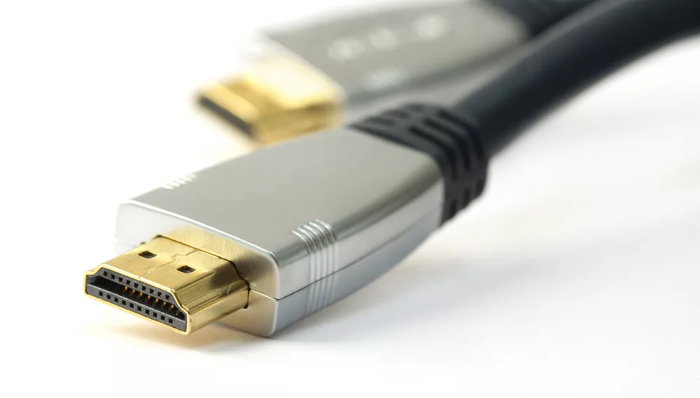
HDMI cable ends
Conclusion:
For DIY HDMI cables, you can get a field installation kit that allows easy installation of high-speed HDMI cables.
You may find a crimper, stripper and HDMI plug in it. With this, you can make a custom-length cable for up to a length of 1’ to 100’.
However, a connector is designed solely for a particular HDMI cable.
If you accidentally use mismatched connectors and cables, you may get no result or even damage your system.
If you need custom-designed HDMI cables and other cables, contact Cloom.