
Often, you find toggle switches in Vehicles. They allow drivers to access headlights, indicator lights, and similar controls quickly. However, what if we need to switch a whole circuit on the toggle switches? After knowing the toggle switch wiring, it won’t be difficult at all.
Table of Contents
- What are Toggle Switches?
- What is a momentary toggle switch?
- How Does a Toggle Switch Work?
- Type of switch
- Toggle switch electrical connections
- Toggle Switch Wiring
- How to Wire a Toggle Switch in Your Car?
- Conclusion
What are Toggle Switches?
Some other names for toggle switches include toggle power and joystick switches. They are versatile gadgets; thus, you can use them with practically any electrical application.
Toggle switches are essential in circuits where you have multiple devices attached to them. This helps in alternating the current path between different loads manually or automatically.
They provide on-off control by cutting off and re-establishing the flow of electricity in electrical circuits. You can set it up by withdrawing a contact surface from the terminal or putting the two back into contact.
The circuit is complete and lives as soon as you contact, allowing electricity to flow and power the attached item. Then, the device is turned off since the circuit opens, breaking the flow of current when the connection is pushed away again.
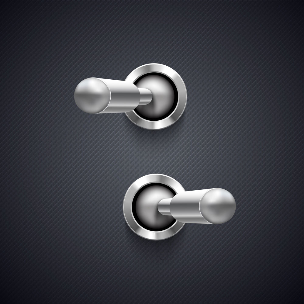
Caption: Metallic toggle switch
What is a momentary toggle switch?
Momentary switches are spring-loaded switches that, once released, flip the toggle back off. Most toggle switches have a short variant, indicated by parentheses – e.g. (on)-off-(on).
Additionally, momentary toggle switches are typically rated for 12V or 15A.
How Does a Toggle Switch Work?
The toggle switch structure is essential, although you can get it in various forms and settings.
The “toggle” in a toggle switch is the movable hinge, handle, or lever mechanism that allows the button to transition on and off. A latch ensures that it stays in place after you relocate it, so you can set it where you need it and forget about it. So, when you pull the toggle, an armature (a part conducting electrical signal) attached to it moves. It makes or breaks the electrical contact from a circuit and, thus, activates or deactivates the circuit.
Even though the temporary switches have an associated spring that will make the actuator return to its original point if released, the button will typically stay in place unless manually pushed again.
Type of switch
Toggle switches are available in multiple designs for use in different settings.
On-On Toggle Switches
With the On-On switch, you can activate two devices simultaneously. You may also know it as changeover switches. This On-On switch combines the spring-loaded system with a standard click position that snaps back if not kept in place.
On-Off Toggle Switches
One of the basic designs is giving you a simple, binary on/off switch for the power supply. So, when you move it from one position to the next, on/off toggle switches typically generate an audible clicking noise. Some people call them “positive” on-off switch types.
On-Off-On Toggle Switches
The on-Off-On Toggle switch is a variation of the on-on design. It has the third neutral off in the middle, which is the default resting position of the button. Thus, once disengaged, both the on and off classes will return to the off position.
Toggle switch electrical connections
Single and double poles have abbreviations SP and DP, whereas single throw and double throw are ST and DT.
The term “pole” describes how many power systems a switch can control. While the SP switches limit to just one, the DP switch can manage two separate circuits while acting as two switches connected mechanically. However, you should not confuse “pole” with “terminal.” For instance, the DPST switch has four terminals. It is DP or double-pole, rather than being a 4P switch.
ST switch can only complete a circuit at one point, referred to as the actuator’s “throw” position. Here, the other point of the handle is the OFF handle’s different position is Off. Moreover, the DT switch can complete the circuit in the Up and Down (On-On scheme). Other than that, a center position may also be present that can open the course (frequent On-Off-On).
You usually find the switches that are single pole/single throw and double pole/double throw. However, triple and quadruple combinations are available in the market and can be used in complex circuits. Their frequent designations are 3PST (3-pole single throw), 3PDT, 4PDT, etc.
Here are some electrical connections that distinguish the various toggle switch models.
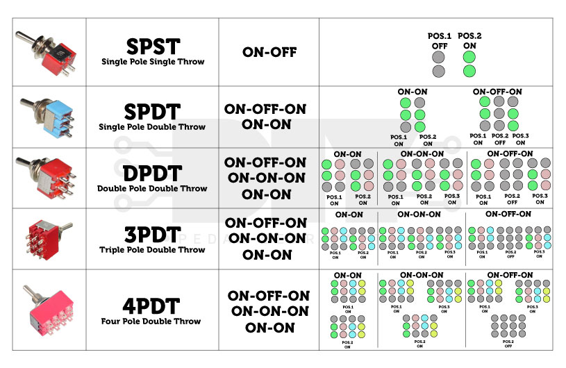
Caption: different versions of toggle switches
Source: https://www.diypedalgearparts.com/en/novita/23_Switch-a-levetta-dal-punto-di-vista-elettrico
Toggle Switch Wiring
Here are some typical wiring designs of the Toggle switches
SPST Toggle Switch Wiring
The SPST toggle switch has only two connections. The input goes into terminal 1, and the output goes out of the other end.
SPST toggle switches turn things on and off. When they are open, they break the circuit so electricity can’t get to the load. Hence, electricity can flow and run through the bag when you close the switch.
Below is an example of how an SPST toggle switch works:
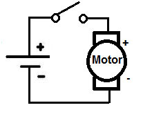
Caption: Wiring Diagram for an SPST toggle switch
Source: http://www.learningaboutelectronics.com/
You can see that this circuit is just an ON/OFF switch that turns the DC motor on and off.
SPDT Toggle Switch Wiring
There are 3 connections on an SPDT toggle switch. Also, you can attach any load into Terminals 1 and 3 to power a device. Terminal 2 is the one that gets the power essential to energize the loads on terminals 1 and 3. So an SPDT switch can energize either one of two circuits. Also, it can change the current between the two circuits so that you can power different devices by just flipping a switch.
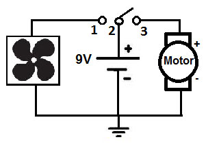
Caption: SPDT Toggle wiring circuit
Source: http://www.learningaboutelectronics.com/
In the circuit above, we connect the 9-volt Dc supply to terminal 2. Terminal 2 is the switch that lets us switch between Terminals 1 and 3. Then, a fan is linked to Terminal 1, so when we move the toggle to the left, the DC fan runs, but the DC motor doesn’t. On the other hand, when we move the toggle to the right (terminal 3), the DC motor runs, but the fan doesn’t. Hence, with an SPDT switch like this, we can control two different components or devices since the double-throw switch gives you two choices.
DPDT Toggle Switch Wiring
There are six terminals on a DPDT toggle switch. The toggle switch is represented by terminals 3 and 4. Terminals 1 and 5, as well as 2 and 6, receive power from these terminals. Flipping between terminals 1 and 5 is possible with terminal 3. The toggle switch can choose between powering the fan or the motor if the fan is connected to terminal 1 and the engine is connected to terminal 5.
Terminal 4 works the same as 3, 2, and 6 and powers them. Terminal 2 connects to a heater, and terminal 6 connects to a blower; you can toggle switch 4 between the two. The two input switches on a DPDT switch can be connected to either terminal. As a result, two buttons can operate up to four distinct circuits or devices.
Below is an example of a DPDT toggle switch circuit:
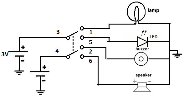
Caption: An illustration of a DPDT switch circuit
Source: http://www.learningaboutelectronics.com/
You can see from the diagram above that we can toggle between four separate circuits using only two switches. Hence, you will activate the lamp and buzzer while flipping the switch in one way and activate the LED and speaker the other way around.
DPST Toggle Switch Wiring
It has four terminals (L1, L2, L3, and L3), referred to as L1, L2, and L3. All incoming lines and the load appliances (normally L3 and L4) connect to L1 and L2 terminals.
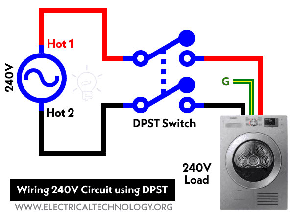
Caption: Wiring 240V circuit using DPST
Source: https://www.electricaltechnology.org/
AC load appliances (such as dryers, water heaters, etc.) are connected to a DPDT switch in this schematic’s wiring diagram. The dryer is directly linked to the ground wire. So that both the Hot 1 and Hot 2 for 240V can be connected directly to the double pole, single throw switch as illustrated, there is no need for a neutral wire.
Both hot wires will be disconnected when the DPST switch is turned off. Both hot wires will be connected when the switch is ON.
How to Wire a Toggle Switch in Your Car?
You can use the toggle switch in your cars as well. How? Fix it in your remote start system so that you can start the engine while standing meters away from it. As you restart the remote, you have to reprogram it. For that
- Turn the ignition “on” while keeping the engine off.
- Locate the programming/Valet switch behind the hood lever release or under the driver’s dashboard.
- Press and then release the switch five times to turn the programming mode on.
- Now, keep holding the programming switch while setting the button up.
- Once done, you can press the “*” button on your remote. It will chirp to indicate that the programming was successful. Release the programming button after that.
Conclusion
The toggle switch helps switch the current path between two devices. While it is used on many devices, you can also use it in cars to elevate the remote start experience. At Cloom, we offer wiring harnesses and cable assemblies to make connections safe and reliable.