
A high-voltage spike happens when the magnetic field of a relay loses power. This increase may damage on-board computers and other delicate equipment. Relays are smart if your device has such components to protect that. Because of this, you may find them in the highest-quality light and wiring systems. Let’s dig into the details of How to Wire a Relay Switch!
Table of Contents
- What is an Auto Relay?
- Application & Advantages of Automotive Relays
- How does an auto relay work?
- Micro Relay vs. Standard Relay/Mini Relay: What’s The Difference?
- Relay Body Markings
- Relay Configurations and types
- Different Functions of relays
- How to wire a relay switch?
- Conclusion
What is an Auto Relay?
An auto relay is essentially just an electrical switch. They use a mechanical switch and an electromagnet device to build or disconnect an electrical circuit. All different kinds of vehicles, including cars, trucks, buses, trailers, and boats, contain them.
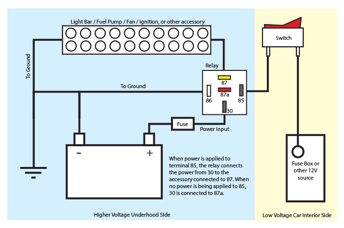
Caption: an example of a relay wiring diagram
Source: https://www.wiringdepot.com/blog/Using-Relays-in-Automotive-Wiring
Application & Advantages of Automotive Relays
Relays can assist you in improving the performance and dependability of an electrical system.
Switching High Current Circuits
Automotive relays are most frequently used to switch a high-power circuit with a lower-power course. This use arises when an inline switch cannot manage the current necessary to activate a high-current system. For example, the current loom configuration capacity may exceed if the work lamps turn on with headlight activation. You can resolve this issue with a vehicle relay.
Activating Multiple Circuits via a Single Switch
You can trigger multiple relays at once in a relay. Moreover, with only one input signal, these relays close or open many circuits and carry out numerous tasks.
Execution of Logic Functions
Auto relays can be used for both straightforward and more complicated logical activities, including temporary inputs and time-controlled operations, such as the timing of interior lights and windscreen wiper functioning. Relays provide a clear and affordable alternative to programmed logic, which manufacturers have mostly abandoned for these jobs.
Save Money
Electrical circuit components with high current costs are high. However, low-present parts cost substantially less. Using an auto relay, you can restrict the deployment of high current circuits to the system’s key components.
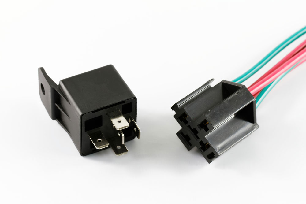
Caption: relay harness
How does an auto relay work?
Knowing the Electromagnetic Relay Structure helps you get the idea.
The solenoid that has a soft iron core with a coil of wire around it is the essential component of an electrical magnet relay. Also, it has a low-resistance iron yoke, contacts, and a moveable iron armature. The collar is connected to the moveable contacts via a hinged armature. Depending on the relay’s configuration and intended use, there may be more than one set of contacts.
While the spring holds the armature, the de-energized relay creates an air gap in the circuit. That way, contacts physically close one and open another connection. Moreover, as per design, relays can have more or fewer contacts. A magnetic field occurs when you apply the current to the solenoid. This field activates the armature, and the resulting activity of the terminals either breaks or makes the circuit.
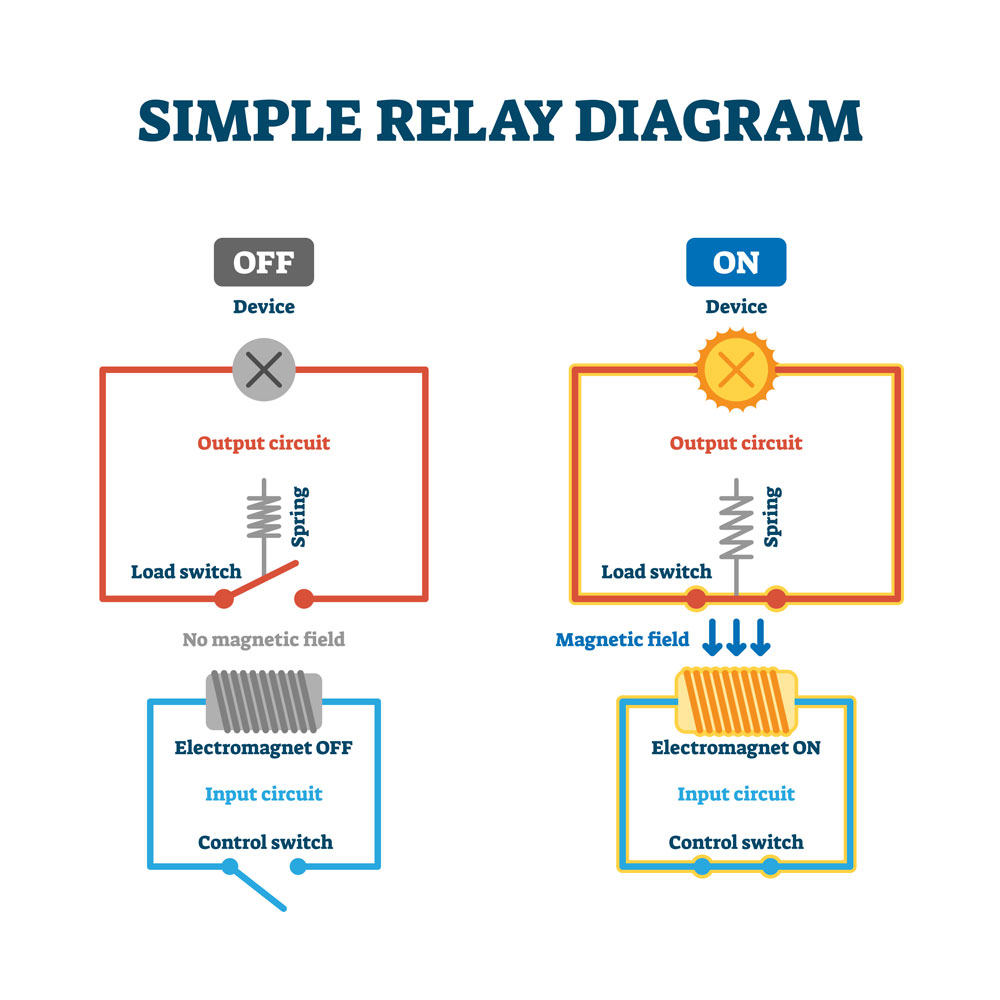
Caption: Working principle of relays
Micro Relay vs. Standard Relay/Mini Relay: What’s The Difference?
Most cars use a compact cube-shaped mini relay or a standard relay. Why? Will micro relays work better?
Standard Relay/Mini Relay
The ISO small relay, which has four or five pins (or terminals) on its body, is known as a make-and-break relay /Single Pole Single Throw (SPST) or changeover relays/ Single Pole Double Throw (SPDT). It has a contact and a high circuit current that can be either open or closed according to the relay inactivation or power. The term “Normally Open” (NO) refers to a relay that opens when it is at rest. Whereas “Normally Closed” (NC) refers to a relay that is closed when it is at rest. The more prevalent form is ordinarily open relays.
Each pin or terminal of a relay has a specific purpose identified by a number code according to DIN 72552.
- 30 Feed/ Line In Positive
- 85 Relay Coil Negative
- 87 Common Contact (NO)
- 86 Relay Coil Positive
- 87a Normally Closed Contact (NC)
The automotive ISO mini relays are typically available in Type A and Type B layouts. And the terminal widths used on 4 and 5-pin relays are almost always 6.3mm wide.
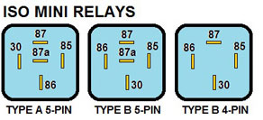
Caption: pin layouts of mini relays
Source: https://www.counterman.com/vehicle-electrical-systems-relays/
Micro Relay
Micro relays are a great option when space is at a premium, such as in an ATM fuse box. Compared to the square-cubed shape of the conventional relay, they feature a more compact rectangular shape. Micro automobile relays employ a varying number identification scheme compared to traditional, tiny relays.
- 5: (6.3mm) Normally Open (NO)
- 4: (4.8mm) Normally Closed (NC)
- 3: (6.3mm) Common Connection to Terminals
- 2: (4.8mm) Coil
- 1: (4.8mm) Coil
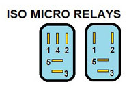
Caption: pin layouts of micro relays
Source: https://www.counterman.com/vehicle-electrical-systems-relays/
Relay Body Markings
Relays might appear somewhat similar externally. But, to help identify these, they typically feature markings on the body.
Circuit diagram: It helps to wire and displays the internal virtual circuits (with any resistors, diodes, etc.).
Voltage rating: The high current circuits and coils are usually present in passenger cars and small boats. The standard voltage for such vehicles is 12V, although 6V and 24V options are also available. However, these options are usually for vintage machinery and commercial applications.
Current Rating: It tells about the amount of current it can easily pass through and is generally in the range of 25A to 40A. Some cases also show dual ratings like 25/40A for changeover relay circuits.
Terminal Numbers: The circuit design usually has the tag with 85, 30, 86, 87, and 87a (to identify various relay setups) on plastic adjacent to each contact.
Relay Configurations and types
- Make & break relay: These are the most simple form of relays that have a connection on terminals 87 and 30. This circuit connects when given energy and disconnects upon de-energizing the system.
- Changeover relay: Two circuits at 87 and 87a terminals connect to terminal 30. It also changes upon energizing and de-energizing the system. Moreover, it cannot combine both courses to terminal 30 simultaneously.
- Relay with double output: In this type of schematic, there are dual output terminals 87 and 87b with signal NO contact. Thus, when input is powered, it connects to one output, and upon rest, it connects to another.
- Relay with dual contacts: It works the same as the above. However, it can provide the output to the 87 and 87b terminals when powered.
- Relay with integrated amp fuse: This schematic has ceramic plugs connecting the inline fuse in the circuit, thus providing built-in protection to the system.
- Relay with a diode across the Coil: When you remove the voltage on terminal 85/86, a magnetic field collapses around the Coil. It can result in higher voltage movement around the circuit, damaging the equipment attached to it. Thus, the schemes use diodes along the course to avoid high voltage spikes. That way, it provides a safe path to the high-current equipment.
- Relay with a resistor across the Coil: Some schemes use resistors to avoid voltage spikes like diodes. However, the resistor does allow some current to pass through and can result in damage. Also, they are not sensitive to polarity, making it not a good choice for these circumstances.
Different Functions of relays
Relays can function under different circumstances making their application broader. Some unique types include.
Time-Delay Relays
Relays with a time delay come in handy when a component needs to be powered for a predetermined period or after a predetermined delay. These relays are ideal for various time-based applications since they provide built-in time-delay capability. Different time-delay relay types are included in this category, each with a unique application. These are,
- On-delay Timers that work on a set wait time
- Off-delay Timers that require a trigger to activate
Sequential Relays
Multiple components can be powered sequentially through relays, often in a predetermined order. This relay is frequently used to sequence power supplies or power various systems or groups of lights, such as in runway lighting.
Automotive Relays
Relays are used in various automobile applications, including several of the relay types mentioned. Additionally, numerous automotive relays enable designers to incorporate cutting-edge security measures and contemporary electrical comforts.
How to wire a relay switch?
A relay connects the high-amp component to a pure 12V source and is effectively a heavy-duty switch. The relay will power the accessory once started using 12V power and ground. If the battery is relocated to the back of the car, find the relay/fuse bank nearby and run a 20–18 gauge wire to the cockpit to activate the relays.
Wiring Diagram
Relays and their connections can vary. Make sure the relay wiring diagram first. Take a type B 4-pin relay, for Example:
- 12V triggers from terminal 86
- Trigger on the ground from terminal 85
- 12V source at terminal 30
- Device connection to terminal 87.
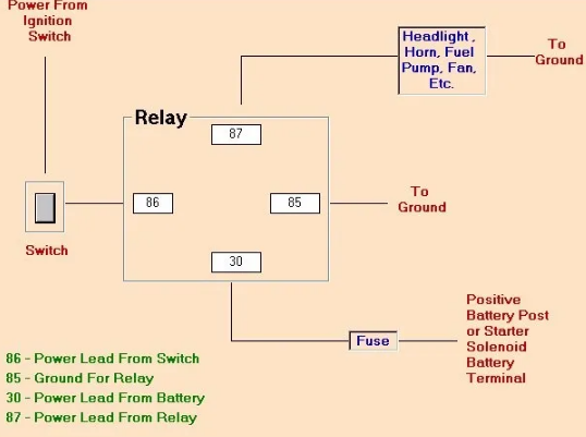
Caption: an example of a relay wiring diagram
Source: https://www.pomonaswapmeet.com/blog/2014/05/15/tech-tips-from-capps-hot-rods-why-use-a-relay/
Steps to wire a relay
Step 1
Disconnect the car’s battery from the circuit.
Step 2
Install the relay in the area that is accessible. In the case of the moist region, you have to use waterproof connections.
Step 3
Use a 12 to 14-gauge wire (preferably red to indicate hot wire) and a ring connector and connect its one end to the battery’s positive terminal. Link the other end to terminal 30 of the relay using a spade connector switch. Also, add an inline fuse between the connections.
Step 4
Install a spade connector to the “hot wire” of a nearby power source.
Step 5
Take a black 16 to 24-gauge wire and crimp a spade connector on one side of it. Connect this to the relay terminal 86.
Step 6
Install the ring connector on the other side of the black wire and connect it to the ground near the relay.
Step 7
Take another long wire and connect its one end to terminal 85 while connecting the other side to a switched current source.
Step 8
If the component needs a switch, add it to the terminal 85 connection.
Step 9
After all the connections, restore the battery and turn on the ignition.
Step 10
While the ignition is on, test terminal 87, for the voltage should read 12V. As the work is done, make the final connection to terminal 87 and check for its functioning.
Conclusion
The number of relays in a car may vary depending on the features that have been added. Among them, some relays are the best option for complete voltage applications. They allow different current levels to operate simultaneously, like a car’s horn, auxiliary lamps, headlights, fan cars, etc. At Cloom, we offer wiring harnesses and cable assemblies to make your connection reliable and safe.