
The Micro USB connector system has been in use for a while, and recently, companies introduced its latest version as micro-USB Type-C.
Most new smartphones manufactured today come with a micro-USB C port. It has become popular mainly due to its port compatibility with both sides, which means you can insert it from any side, upside or downside.
In this article, we will learn the USB-C wiring diagram so that we can know about how the USB-C cable works.
Table of Contents
- USB C/USB-C-to-USB-A cable understanding:
- USB-C cable wiring diagram with Type A USB 2.0 male:
- USB-C wiring diagram with male USB 3.1 and 3.2 Type A (Generation 1 and 2)
- Conclusion:
USB C/USB-C-to-USB-A cable understanding:
Buying a USB-C-to-USB-A cable (male) will accompany a cell phone charger. You can transfer data to and from computers and also charge your smartphones.
In the USB-C-to-USB-A cable, the type A end connects with the computer and the USB-C end connects to the peripherals devices. It means USB Type A is a downstream connector while USB-C is an upstream one.
There are two versions of these cables: USB 2.0 and USB 3.0. Out of these two, USB 3.0 supports a high data transfer rate and allows more connections than USB 2.0.
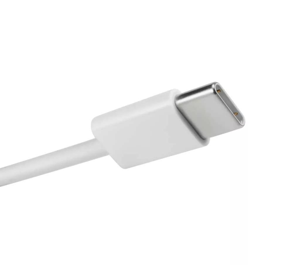
USB Type C end
USB-C cable wiring diagram with Type A USB 2.0 male:
Most cables can support a USB 2.0 data transfer rate (470Mb/s) and power delivery (500 mA, a total power delivery of 2.5 W at 5 V).
What’s inside a USB 2.0 cable?
Inside a USB cable, commonly, you will find four different colored wires: red, black, white and green.
Every wire has its unique purpose.
Out of these four wires, the white wire is Data + or D+, and the green wire is Data- or D-. As the name clears, both these wires help in data transfer.
Further, the red wire is a power wire with +5 volts of DC supply to power the USB device.
Lastly, the black wire is GND or grounding wire, which prevents the devices from electrical shocks.
Some USBs do not follow this combination of wire colors, and you can find another combination of blue, green, white and orange wires in such USBs.
Here, the white one is the ground wire and the orange wire supplies power with its +5 Volts DC power. The remaining green and blue are positive and negative data wires, respectively.
Pin definition of four-pin USB 2.0 A:
The Type A connector has four pins. Its female version is like a USB connector pinout as you see a keyboard connector, while the male version has a USB port pinout like your laptop ports.
Pins are arranged in descending order in the female port, starting from the right side, while the male port has the opposite order.
| Pin | Signal | Description |
| 1 | VCC | +5 Volts |
| 2 | Data – | Data positive |
| 3 | Data + | Data negative |
| 4 | GND | Ground |
As you know, everything is the same except the pin order in the USB port and USB connector. The table above shows the USB pin arrangement for USB connectors only; for the USB port, you have to reverse the order.
Pin definition of 24-pin USB Type-C
Here, we will mainly focus on the male connector in the USB-C cable.
The table below shows that the pin’s position with the same functionality is diagonally symmetrical with the center point.
Thus, once you insert the male and the female connector, the pins fit seamlessly, irrespective of the insertion direction.
| Pin No. | NAME | Description | Pin No | Name | Functional description |
| A1 | GND | Ground or drain wire | B12 | GND | Ground or Drain wire |
| A2 | SSTXp1 | Superspeed differential signal no.1Tx positive | B11 | SSRX p1 | Superspeed Differential signal no.2Rx positive |
| A3 | SSTXn1 | Superspeed differential signal no.1Tx negative | B10 | SSRXn1 | Superspeed differential signal no.2Rx negative |
| A4 | VBUS | Voltage supply | B9 | VBUS | Voltage supply |
| A5 | CC1 | Configuration channel | B8 | SBU2 | Sideband use |
| A6 | Dp1 | USB 2.0 differential signal, positive (position 1) | B7 | Dn2 | USB 2.0 differential signal negative (Position 1) |
| A7 | Dn1 | USB 2.0 differential signal position 2, positive | B6 | Dp2 | USB 2.0 differential signalPosition 2, positive |
| A8 | SBU1 | Sideband SUe | B5 | CC 2 | Configuration channel |
| A9 | VBUS | Voltage supply | B4 | Vbus | Voltage supply |
| A10 | SSRXn2 | Superspeed differential signal no.2Rx negative | B3 | SSTXn2 | Superspeed differential signal no.2Tx (negative) |
| A11 | SSRXp2 | Superspeed differential signal no. 2 RX positive | B2 | SSTXp2 | Super Speed differential signal no. 2 TXpositive |
| A12 | GND | ground/drain wire | B1 | GND | Ground or drain wire |
The power supply GND/VBUS has four pins each, which can supply power simultaneously. As a result, USB-C can achieve 5 Amperes high current supply.
USB C 2.0 Cable Wiring Diagram
The following table shows the connection between PINs at both ends.
| Pin No ( USB A) | Pin no (USB-C) | Codes of wire | Details | Symbol |
| 1 | A4, A9, B4 and B9 | Red | +5 volts (DC supply) | VCC (virtual common collector) or VBUS |
| 2 | A7 | White | Data negative (from equipment to host) | D-ve |
| 3 | A6 | Green | Data positive (from host to equipment) | D+ve |
| 4 | A1, B1, A12, B12 | Black | 0V (ground pin) | GND |
| NC | A5* | N | Configuration channel 1 | CC1 |
USB-C 2.0 Cable wiring diagram explained:
- Based on the USB standards, the power supply in the USB-C cable is +5 volts. However, the capacity of maximum current output can differ for different versions.
- The USB A PIN 1 connects to the Pin No. A4, B4, A9 and B9 of the USB-C port. It’s the VBUS/+VDD power supply pin. This pin supplies power to the equipment or the device it connects. It is also an indicator that shows that the cable is connected to the equipment.
- The USB standard A Pin Number 4 connects to the micro-USB-C Pin Number A1, A12, B1, and B12. This is a Ground supply or GND pin.
- The USB A Pin Number 3 connects to the micro-USB Type C Pin Number A6, named a differential data negative pin.
- The last type, Pin number 2, connects to Pin Number A7 of the USb-C. This is a differential data positive pin. Through Pin number 2/Pin A7 (D-) and Pin number3/Pin number A6 (D+), data transfer (to and from) takes place in a specific USB protocol.
- The color codes for Pins 4,3, 2, and 1 are black/gray, green, white and red in the USB-C cable.
- In some USB cables, a few manufacturers do not connect Pin Number A5 to any part of the USB-C side cable. It helps them reduce money and time, but all good quality cables have their A5 connection.
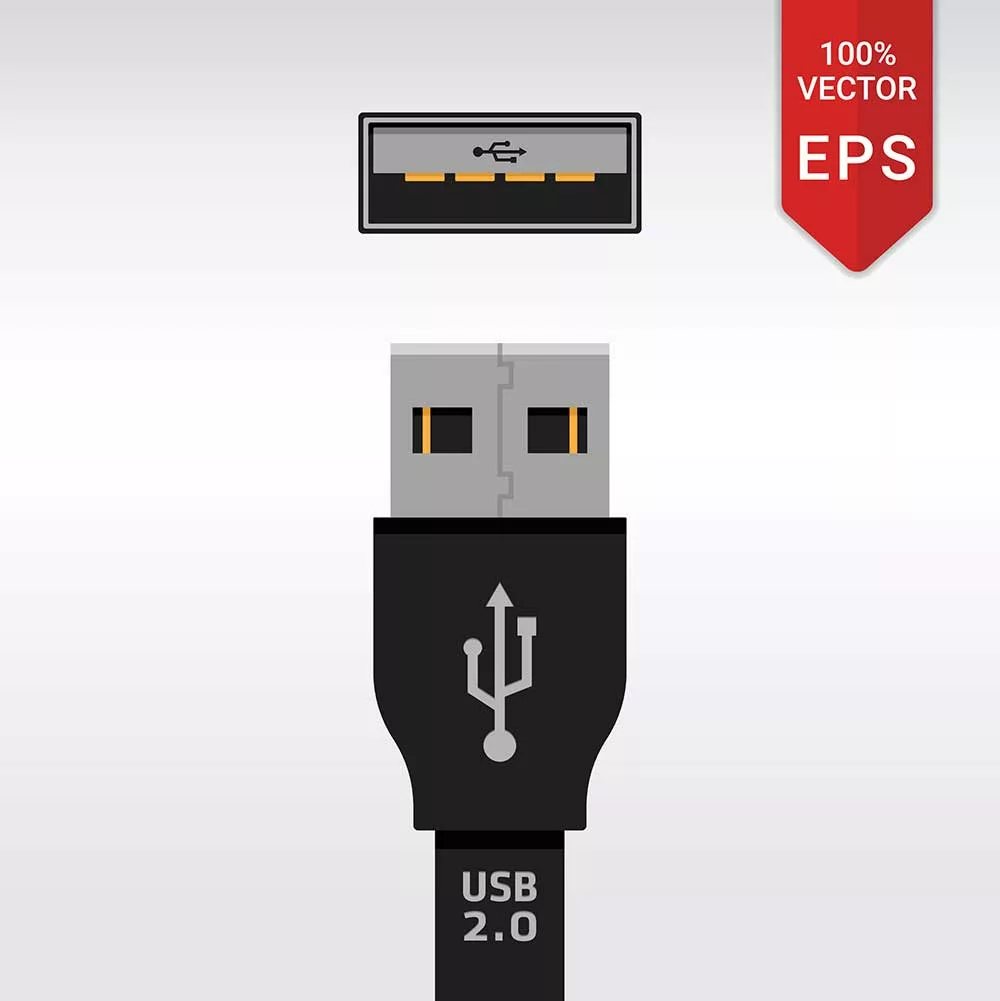
USB 2.0
USB-C wiring diagram with male USB 3.1 and 3.2 Type A (Generation 1 and 2)
Most cables can support USB 3.0 data transfer rate (5gbps-10gbps) and power delivery( 900 mA, a total power delivery of 4.5 W at 5 V).
What’s inside a USB 3.0 cable?
In the USB 3. x version, you get very high speed due to 5 more wires added to its wiring.
Among these 5, two are in pairs: one pair for Tx( TX+ and Tx-) and another one for RX (RX+ and RX-), and the remaining wire belongs to the ground return.
The wire gets new color codes other than USB 2.0 wire colors for easy identification. Also, USB 3.0 is a fully functional cable with 8-10 wires/bus for connection.
Pin definition of 9-Pin USB A 3.0:
The USB 3.0 version of Type A has nine pins, making it a superspeed version.
Also, in USB 2.0 and 3.0 Type-A connectors, the extra five pins are arranged to be completely compatible and interchangeable without any issues.
| Pin | Color | Signal | Description |
| 1 | Red | VCC | +5 volts DC supply |
| 2 | white | D- | Data negative |
| 3 | green | D+ | Data positive |
| 4 | Black | GND | ground |
| 5 | Blue | StdB_SSRx- | Superspeed transmitter differential negative |
| 6 | yellow | StdB_SSRX+ | Superspeed transmitter differential positive |
| 7 | N/A | GND | Ground return |
| 8 | Purple | StdB_SSTX- | Superspeed receiver differential negative |
| 9 | orange | StdB_SSTX+ | Superspeed receiver differential positive |
Pin definition of 24 pins USB C 3.0:
| Color of the conductor | Pin at Port | Signal Name |
| red | A4, B4, B9, A9 | VBUS/VCC |
| white | A7 | Dn1/D negative |
| green | A6 | Dp1/D positive |
| black | A1, B1, B12, A12 | Ground |
| N/A | A5 | Configuration channel |
| N/A | B5 | VCON |
| Blue | A3 | TX 1 negative |
| yellow | A2 | Tx 1 positive |
| purple | B10 | Rx1 negative |
| N/A | GND | Ground |
| Orange | B11 | Rx1 positive |
| N/A | Shell | Shield |
The parameters and terminologies of USB C 3.0 for manufacturing/technical use.
Rp or pull-up resistor: The A5 pin connects to the resistor Rp in series with the VBUS power supply at the USB-C plug terminal.
The resistor has a resistance of 56 ohms, and its value decides the current carrying capacity of the port for which the plug is designed.
SHIELD/SHELL/BRAID: High-quality cables have a 390-degree conductive cover and ground shield termination on wires. As a result of this, wires get protection against any RF interference and crosstalk from nearby data lines.
Generally, A6 and A7 are unshielded wire pairs, while B10 + B11 and A2 + A3 are shielded pairs.
Here, both shields of the shielded pairs are grounded individually, while the ground connection is a separate conductor in black color.
USB C 3.0 Cable Wiring Diagram
The following table shows the connection among PINs at both ends.
| Signal Name | Port no. 1 | Color of the conductor | Port no. 2 | Signal name |
| Vbus | 1 | Red | A4, B4, A9, B9 | VBUS |
| D- | 2 | white | A7 | Dn1/data- |
| D+ | 3 | Green | A6 | Dp1/data + |
| GND_DRAIN | 4 | Black | A1, B1, A12, B12 | GND |
| N/A | – | N/A | A5 | CC |
| N/A | – | N/A | B5 | VCON |
| SSRX- | 5 | Blue | A3 | TX1- |
| SSRX+ | 6 | Yellow | A2 | Tx1+ |
| SSTX- | 8 | Purple | B10 | Rx1- |
| GND_Drain | 7 | – | GND | GND |
| SSTX + | 9 | Orange | B11 | Rx1+ |
| Shield | SHELL | N/A | SHELL | SHIELD |
USB-C 3.0 cable wiring diagram explained:
- Based on the standards of USB, VBUS supplies +5 volts power and a default current output of about 3 Amperes.
- Pin Number (USB A version 3.1) connects to the Pin Number A4, B4, B9 and A9 of USB-C. The Pin’s name is VBUS or VCC, and it supplies power to the equipment or device it connects to.
- Pin Number 4 of the USB 3.1 connects to the Pin NumberA1, B1, A12, and B12 of the USB-C port. It is a Ground Return pin represented by a separate black wire.
- Pin Number 3 of the USB Type A 3.1 connects to the Pin Number A6 of the USB-C port. Pin No. 2 of the Type A port connects to Pin Number A7 of the USB-C port. Both these pairs, 2/A7 and 3/A6 are D- and D+ pins. In USB 2.0 version mode, these differential data pins help to send and receive data from the ports.
- Pin number 7 connects to the Shell/Drain.
- Pin 5 of port 1( USB Type A 3.1)i.e. SSRX- connects to pin 3 i.e. TX1- of port 2 (USB-C). Similarly, Pin 5 of port 1, i.e., SSRX+, connects to the Pin A2, i.e., TX1+. Here, SSRX refers to the bidirectional and superspeed data transmitter ends.
- You can write SSRXp1 as SSRX1+ and SSRXn1 as SSRX1-.
- Pin Number 8 of port 1, i.e., (SSTX-) connects to the Pin number B10, i.e., RX1- of USB-C port and Pin Number 9 of port 1 (SSTX+) connects to the B11, i.e., RX1+ of USB-C port. Here, SSTX refers to the bidirectional and superspeed data receiver ends.
- You can write SSTX p1 as SSTX1+ and SSTXn1 as SSTX1-.
USB 3.0
Conclusion:
So, now the internal structure of a USB Type C cable must be clear to you.
We advise picking only high-quality USB Type-C cables from a reputed brand like Cloom.
We always strive to deliver our clients the best quality cable assemblies and wiring harnesses.