
Coaxial cables play a crucial part in the overall performance of an antenna system. They transfer signals from one point to another, and ideally, they should transmit the same amount of power from one point to another. However, this isn’t the case. In real-world situations, there’s signal loss or attenuation, which affects signal strength. This loss is an important feature to consider when selecting a coaxial cable. So learning how to use rf cable loss calculators can help you reduce the amount of signal loss and how to select a low loss rf cable. However, before all that, you need to understand what cable loss is.
Table of Contents
- What is Cable Loss?
- How to measure RF Cable Loss?
- RF Cable Loss Calculator
- Low Loss RF Cables
- Conclusion
What is Cable Loss?
As a signal moves through the cable, some of its power is lost to it and other system components. This power loss is referred to as cable loss. How much cable loss you get depends on the length of the cable and frequency. The longer the coax cable, the greater the loss; however, frequency-wise, the higher the frequency, the greater the loss. Despite this, the actual level of loss is not linearly dependent on the frequency used. Therefore you can define cable loss in terms of decibels per unit length at a given frequency.
There are 3 main ways this power loss occurs:
Resistive loss
Resistive loss occurs when the resistance of the conductors and the current flowing through them generates heat. Since the skin effect reduces the area the current can flow in the conductor, this loss becomes more apparent as frequency rises. This means that resistive loss increases as the square root of the signal frequency. You can increase the cable’s conductive area to reduce resistive loss; that’s why you should use multi-strand conductor cables. This results in low coax cables becoming larger in size.
Dielectric loss
This type of power loss occurs as heat lost within the insulating dielectric of a conductor cable. Unlike resistive loss, this energy loss occurs independent of the coaxial cable’s size and increases linearly with frequency. This means you are more likely to encounter resistive loss at low frequencies while dielectric losses dominate higher frequencies.
Radiated loss
The last kind of power loss occurs due to radiation. When signal energy passing through the transmission line radiates outside the cable, radiation loss occurs. Leakage from the coax cable carrying the signal feed from a high-power transmitter might cause sensitive receivers’ interference. Poorly constructed coax cables are highly susceptible to this kind of loss. They can even cause sensitive receivers or the receiving cable to pick up interference as it passes through electrically noisy places. Radiated loss is a lot less than either resistive or dielectric loss, and you can reduce it by using double or triple-screened coax cables designed to reduce the signal leakage levels.
Radiation power loss is minuscule compared to the other two, so there’s generally less of a concern. When calculating and dealing with rf cable loss, most people focus on reducing restrictive and dielectric losses.
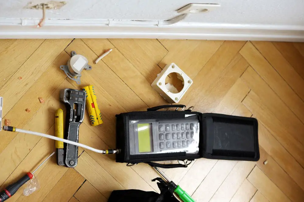
How to measure RF Cable Loss?
A portable vector/scalar network analyzer measures cable loss. This rf cable loss calculator uses the return loss measurement available in the analyzer to calculate the cable loss. Return loss occurs when the signal comes back or reflects due to a discontinuity in a transmission cable. This discontinuity could be another cable or connector. You can think of it as a gauge of how well cables match. The higher the return loss, the lower the power lost through insertion, which occurs when you add a device or cable to the transmission line.
You can measure cable loss by placing the short end of the cable in the meter; once the signal reflects back, you can calculate the power loss of the cable. Most cable and antenna analyzers have a cable loss mode that displays the average cable loss of a particular frequency range. Coax cables with larger diameters have lower insertion loss and thus are better at handling signal power than smaller cables.
RF Cable Loss Calculator
There are two ways you can calculate rf cable loss. These include:
RF cable loss formula
This is a simple formula that you can use to calculate rf cable loss if you don’t have a cable-antenna analyzer.
Cable loss (dB per 100ft) = k1 xF(MHz) + k2 x F(MHz) + CLF x F(GHz)
Alternatively, you could use this formula.
Cable loss = K1 x sqrt(F) + K2 x F (dB/100 feet)
Where,
K1 is the resistive loss constant.
K2 is the dielectric constant.
F is the frequency in hertz (Hz)
CLF is the connector loss factor which is 0.12 for straight-to-straight connections; 0.21 for straight-to-right angle connections and 0.30 for right angled-to-right angle connections.
The cable loss consists of resistive loss, dielectric loss, and connector loss. In the equation, K1 represents resistive loss and relates to the square root of frequency; the dielectric loss denoted as K2 relates to the signal’s frequency and connector loss relates to connectors used. This formula works for both straight type or right-angled connections.
RF cable loss excel
To get k1 and k2 values, you can check out this Excel spreadsheet which shows the best-fit values for k1 and k2 from the manufacturer’s tabular values.
Low Loss RF Cables
Low loss rf cables take the stress out of using rf cable loss calculators when picking which cable to use. While they can’t completely eliminate rf loss, they can deliver a lower attenuation when used in place for similar rf cables in various applications. These cables can offer lower attenuation due to several key factors in their design. These include:
● RF Cable Loss Calculators–A solid inner conductor
The conductor transmits the signal, and to reduce resistive loss, you can use stranded conductors. However, several factors can make the inner conductor less lossy. The primary contributor to cable loss is proximity loss which is the tendency for electromagnetic energy in a conductor to gather away from conductors carrying current in the same direction.
Even though using stranded conductors reduces this multi-conductor version of the skin effect, it doesn’t offset proximity losses. A lack of uniform current distribution increases resistance in the conductor, which increases transmission loss. The solid inner conductor core ensures there’s a uniform flow of current.
● Superior dielectric material
The dielectric material’s main function is to separate the inner conducting core from the outer one while maintaining a uniform cross-sectional dimension transversely through the cable. The signal traveling through the dielectric is slower than the one traveling in free space or even in the conductor; thus, having a cable with a low dielectric constant helps minimize the delay.A simple way to reduce the dielectric constant is by introducing air into the dielectric. You can do this in several ways, such as by helically wrapping the dielectric material around the inner conductor, using spacers, or foaming dielectric material. Introducing air into the dielectric material reduces cable loss by decreasing tangent loss and creating a larger conductor center.
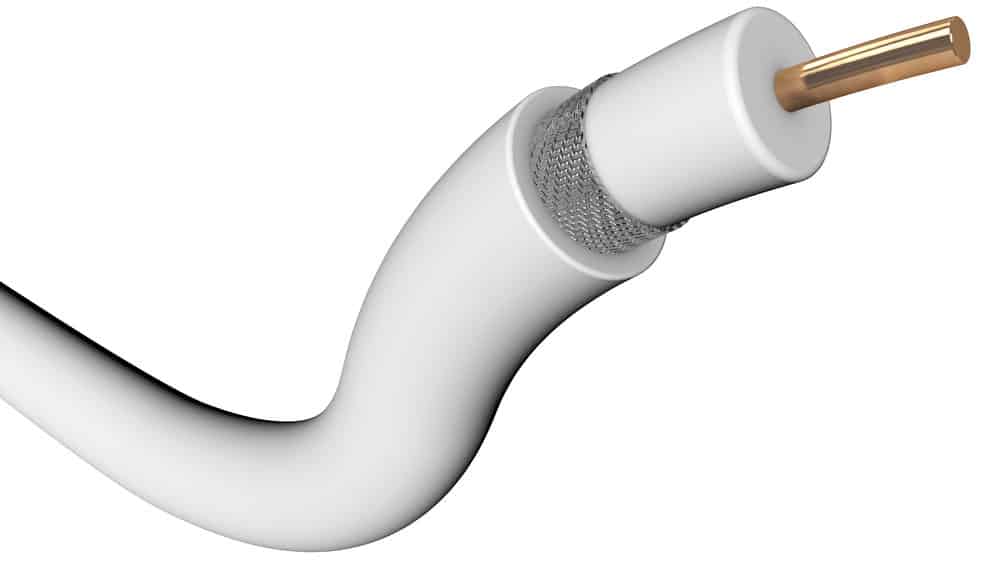
● More shielding
At high frequencies, cable loss will occur, especially if there isn’t any proper shielding. The outer conductor layer acts as a return path for the inner conductor core carrying current in the opposite direction. This creates an electromagnetic shield because it carries equal and opposite signals to those in the inner conductor. The skin effect also plays an important role in shielding, especially in braided cables at lower frequencies.
● Application-specific jacketing materials
By adapting the jacketing material to the environmental conditions, you plan on using the cable in; you can reduce the effects they have on cable loss. These low-loss cables are moisture, vibration, UV, humidity resistant, and sometimes even resistant to chemicals and oils.
Conclusion
Dealing with cable loss can be hectic; however, now that you understand what it is, you can easily calculate it, thus reducing its effect on your system. If you feel like it too much and you would rather let a professional do it for you, we are here to offer cable assemblies attached to connectors, ensuring you won’t have to worry about cable loss.